When the dongle is connected to an inverter/charger and the inverter/charger has been switched on via its main power switch, it takes a bit of time before the dongle detects the inverter/charger. It is initially listed in the VictronConnect device list as a VE.Bus Smart dongle. Once the detection is complete, it will be listed as an inverter/charger. Note that it might be necessary to refresh the device list before the dongle is listed as an inverter/charger.
When the dongle is not connected to an inverter/charger, it is listed as a VE.Bus Smart Dongle. The dongle can be used without being connected to an inverter/charger. In this scenario, it operates as a voltage and temperature sensor and can be used for battery monitoring in VE.Smart Networking.
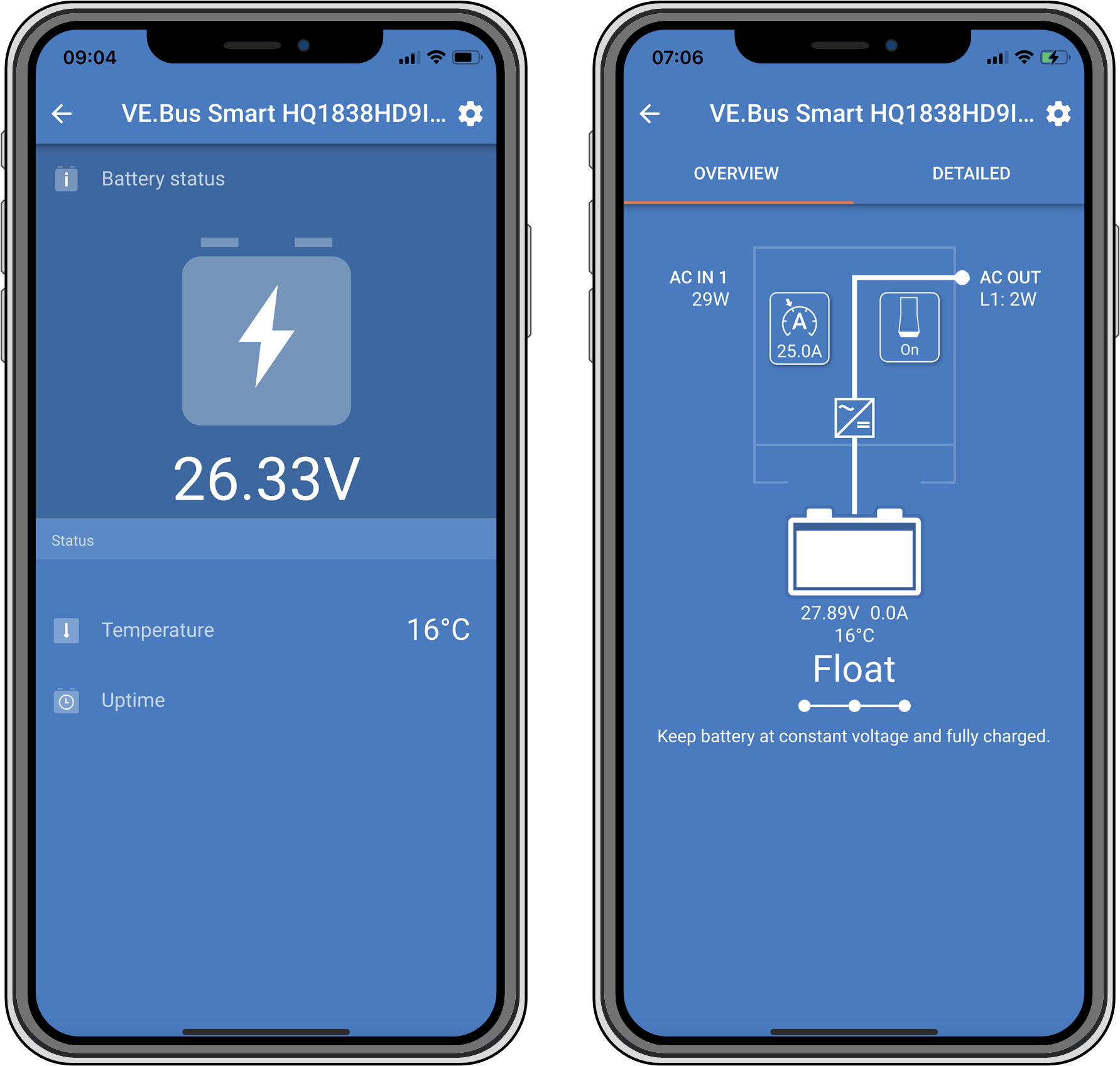 |
VictronConnect screens without and with inverter/charger connected.
The dongle can operate as a primary and as a background information source. It will assume either role automatically depending on whether a GX device is connected to the inverter/charger.
Blue LED | Red LED | Bluetooth connection State | Dongle state |
|---|---|---|---|
Slow blinking | Off | Not connected | The dongle is operational and ready to connect to the VictronConnect app. |
On | Off | Connected | The dongle is operational and is connected to the VictronConnect app. |
Off | Off | Not connected | The dongle is not operational. Probably because it is not powered, check the fuse or the wires between the dongle and the battery connection. |
Fast blinking (alternating) | Fast blinking (alternating) | Not connected | Firmware update. |
On | Slow blinking | Connected | Firmware update. |
On | Fast blinking | Uploading | Firmware update. |
Fast blinking | Off | Programming | Firmware update. |
On | On | Disabled | The dongle is not functional (hardware error). The dongle is not visible in the VictronConnect app and will not transmit battery temperature and voltage to the inverter/charger. |
The dongle can control and monitor the inverter/charger via the VictronConnect app.
The "overview" page contains the following:
The inverter/charger can be turned on, off or set to charger-only mode via the switch symbol as indicated in the below image.
The AC input limit of the inverter/charger can be adjusted via the dial symbol as indicated in the below image.
Battery voltage, current and temperature are shown.
The device status is shown.
More detailed inverter/charger information can be seen on the "detailed" page.
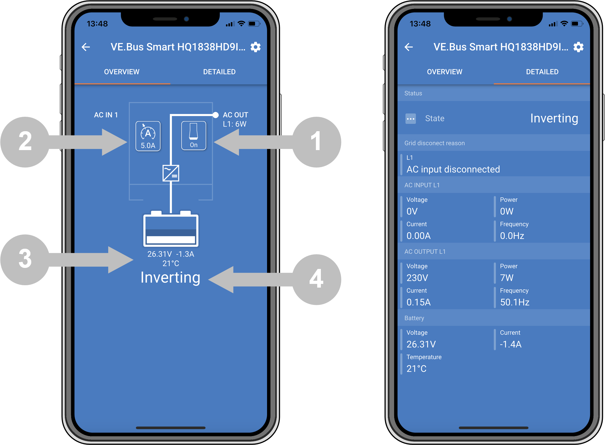 |
VictronConnect app "overview" and "detailed" screens.
Note
Note that if a Digital Multi Contol panel (DMC) is connected to the same system as the dongle, the DMC will override the on/off/charger-only and current limit control features of the dongle. The dongle can only monitor the battery and inverter/charger parameters and act as a temperature and voltage sensor but cannot control the inverter/charger.
The dongle measures the battery temperature and voltage:
The battery temperature measurement allows the inverter/charger, or charge sources that are connected to VE.Smart Networking, to adjust the charge voltage to compensate for battery temperature.
The battery voltage measurement allows the inverter/charger, or charge sources that are connected to VE.Smart Networking, to adjust the charge voltage to compensate for cable voltage losses that can occur during charging.
For more information about temperature and voltage compensation, see the inverter/charger manual.
Note
Note that the inverter/charger does not use the dongle temperature and voltage measurements if the inverter/charger is connected to a GX device and a CANbus battery (smart battery). The data from the smart battery will override the data from the dongle.
In systems with an inverter/charger and GX device but no other source of temperature and voltage, the data from the dongle will be used by the inverter/charger and the GX device.
In systems with a GX device, where another source of temperature and voltage data, e.g. from a CANbus battery (smart battery), the data from the smart battery will override the data from the dongle. In this scenario, the data from the smart battery is used by the inverter/charger and GX device. The dongle will still provide live information via its VictronConnect interface, but the system will use the data provided by the smart battery.
A GX device has priority over the dongle and should always be able to access all data. When power is applied to the dongle, or after a firmware update, the dongle will start up in background mode. The VE.Bus communication ports will be monitored for 30 seconds. If no GX device is detected, the dongle will switch to primary mode, and all supported data will be available. While switching modes, VictronConnect will temporarily indicate an “unknown” VE.Bus state. The dongle continuously monitors the VE.Bus for GX device activity. It will switch itself to background mode as soon as a GX device is detected or changes to primary mode when a GX is not detected.
The dongle monitors the VE.Bus to check if a GX device is supplying the inverter/charger with battery voltage and temperature data. It takes around 4 minutes after power-on or a reset before the dongle decides whether or not to transmit the battery voltage and temperature.
Due to restrictions in the VE.Bus communication protocol, only one device can access inverter/charger data at a time. When connecting with the VictronConnect app to the dongle while a GX device is connected, only the battery temperature and voltage and inverter/charger state are displayed, and the AC voltage, current, and power readings are missing.
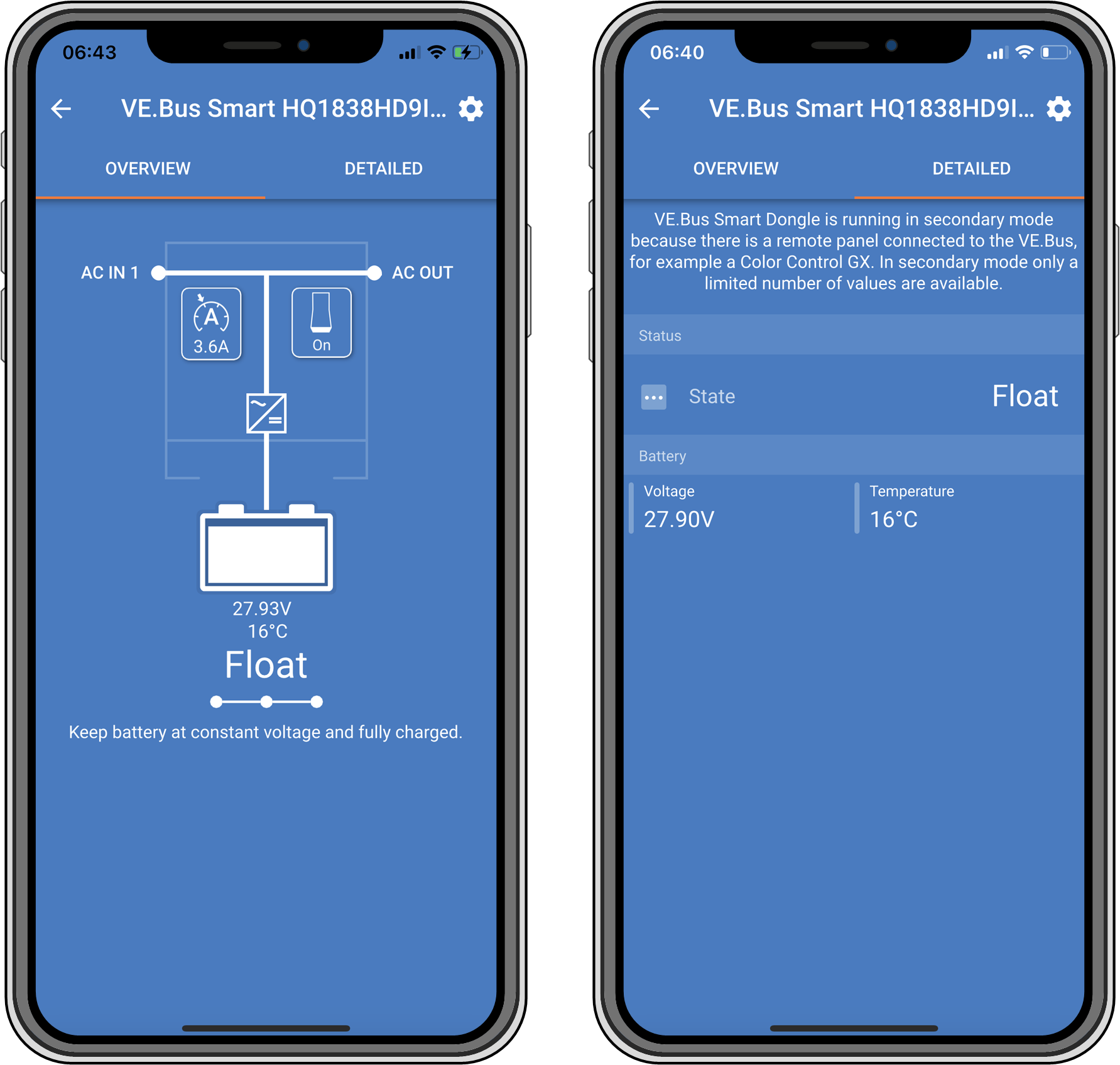 |
VictronConnect screens when the dongle is connected to a GX device.