The isolation transformer eliminates any electrical continuity between AC shore power and the vessel. It is essential for safety and eliminates the need for galvanic isolators and polarity alarms.
Electrical safety is taken for granted in the case of a standard on-shore installation. A circuit breaker will trip, or a GFCI (Ground Fault Circuit Interrupter) will trip in case of a short circuit or a current leakage to ground. Connecting the ground wire of the shore-side supply to a vessel's metal parts will result in galvanic corrosion.
Bringing only the live and neutral wire onboard results in an unsafe situation because GFCIs will not work, nor will a breaker trip in case of a short circuit to a metal part on the vessel.
Galvanic corrosion occurs when two dissimilar metals in electrical contact are simultaneously exposed to an electrically conducting fluid. Seawater and, to a lesser extent, freshwater are such fluids. In general, the more active alloy of the couple corrodes preferentially, while the less active (more noble) material is cathodically protected. The rate of galvanic corrosion is a function of several variables, including area ratios, the conductivity of the fluid, temperature, the nature of the materials, etc.
It is a misunderstanding that galvanic corrosion occurs only in metal and aluminium hulls. In fact, it can occur on any vessel as soon as a metallic part (the shaft and propeller) is in contact with water. Galvanic corrosion will quickly dissolve your sacrificial anodes and attack the shaft, propeller and other metal parts in contact with water when the vessel is connected to the shore-side supply. It might therefore be tempting not to connect the ground conductor: this is, however, extremely dangerous because a GFCI will not work, nor will a circuit breaker trip in case of a short circuit to a metal part on the vessel.
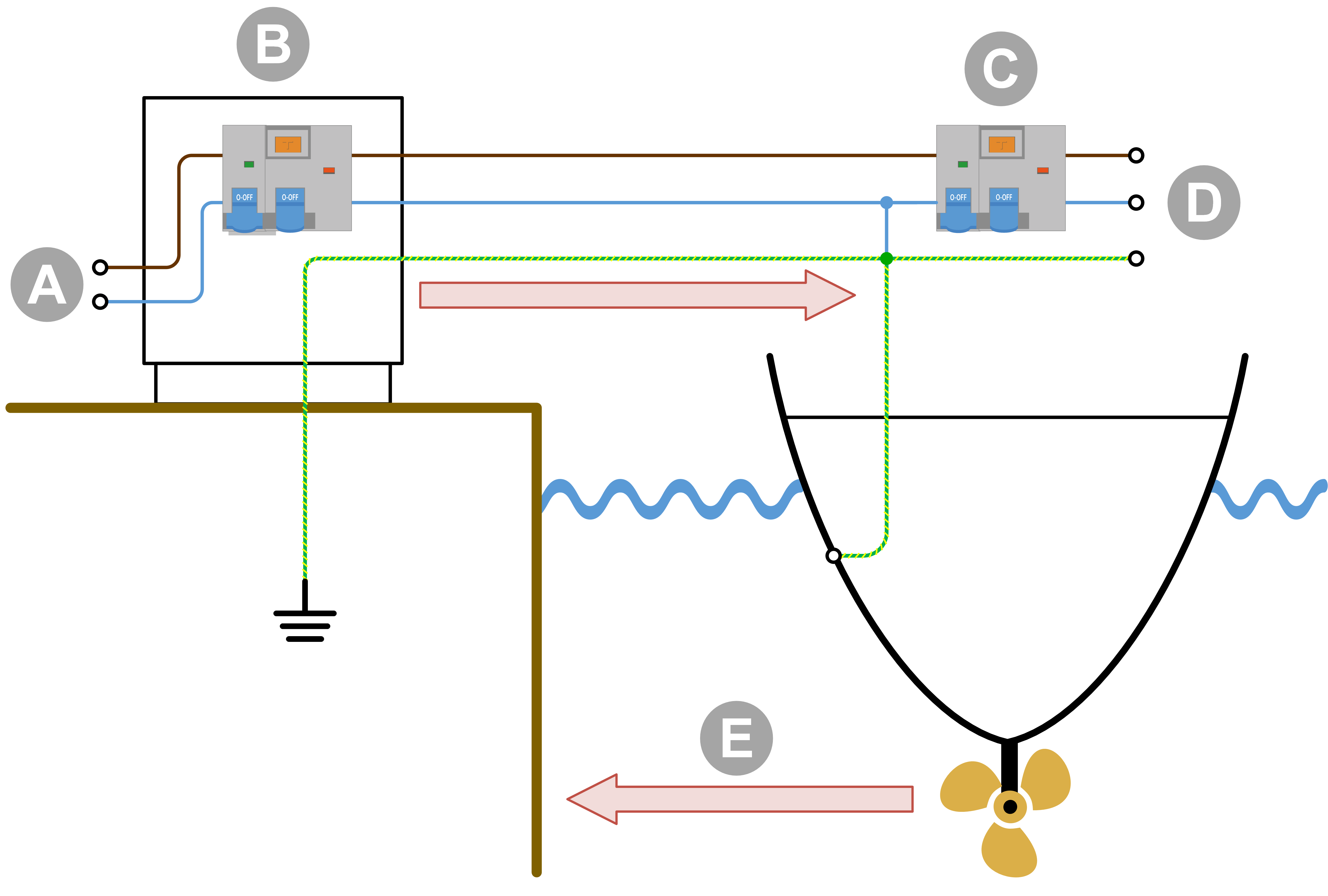
The best solution to avoid galvanic corrosion and, at the same time, prevent any unsafe situation is to install an isolation transformer to connect to the shore-side supply. The isolation transformer eliminates any electrical continuity between shore power and the vessel. The shore power is fed to the transformer's primary side, and the vessel is connected to the secondary. The isolation transformer completely isolates the vessel from the shore ground. By connecting all metal parts to the neutral output on the secondary side of the transformer, a GFCI or a breaker will trip in case of a short circuit.
 The shore ground connected to immersed metals of the vessel causes galvanic corrosion. |
|
 The shore ground is isolated from the vessel ground, and galvanic corrosion originating from the shore connection is blocked. |
|
The isolation transformer converts the input voltage with a 1:1.05 ratio. The 1:1.05 transformer ratio boosts the output voltage of the isolation transformer by 5%. This is to compensate for shore power voltage drops that are a common occurrence in marinas.
The isolation transformer can be used in 115V or 230V systems and also be used to convert 230V to 120V and 115V to 240V. Depending on the isolation transformer configuration:
A 230V input becomes 240V.
A 230V input becomes 120V.
A 115V input becomes 240V.
A 115V input becomes 120V.
The isolation transformer can be used in 50Hz or 60Hz systems. However, the isolation transformer cannot convert frequencies from 50Hz to 60Hz or vice versa.
Soft start is a standard feature of a Victron Energy isolation transformer. It will prevent the shore power circuit breaker from tripping due to the transformer inrush current.
Internal wiring diagram of the isolation transformer. |
|
It is recommended, for optimal safety, to connect the shore earth to the vessel's earth when the vessel is out of the water, in winter or for maintenance. The isolation transformer has a facility for this.
