When switched to “on”, the product is fully functional. The inverter will come into operation and the LED “inverter on” will light up.
An AC voltage connected to the “AC in” terminal will be switched through to the “AC out” terminal, if within specifications. The inverter will switch off, the “Charger” LED will light up and the charger commences charging. If the voltage at the “AC-in” terminal is not within specifications, the inverter will switch on.
When the switch is switched to “charger only”, only the battery charger of the Multi will operate (if mains voltage is present). In this mode input also is switched through to the “AC out” terminal.
NOTE: When only the charger function is required, ensure that the switch is switched to “charger only”. This prevents the inverter from being switched on if the mains voltage is lost, thus preventing the batteries from running flat.
 LED off
 LED blinking
 LED on
LEDs | Description |
|---|---|
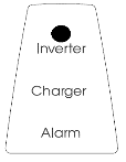 | On / Off / Charger-only switch = On The inverter is switched on and supplies power to the load. |
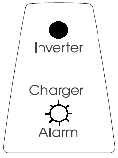 | On / Off / Charger-only switch = On The inverter is switched on and supplies power to the load. Pre alarm: overload, or battery voltage low, or inverter temperature high. |
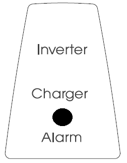 | On / Off / Charger-only switch = On The inverter is switched off due to one of the following alarms: overload, battery voltage low, inverter temperature high, or DC ripple voltage too high. |
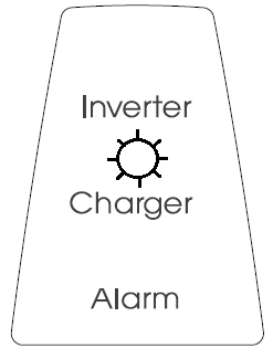 | On / Off / Charger-only switch = On The AC input voltage is switched through, and the charger operates in float mode. |
On / Off / Charger-only switch = On The AC input is switched through and the charge current is zero. The inverter is switched on and, in case of PowerAssist, assists the AC input by supplying additional power to the load the General chapter. | |
On / Off / Charger-only switch = On The AC input voltage is switched through. The inverter is switched on and supplies power to the load or excess power to the mains. | |
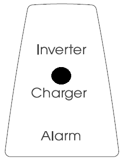 | On / Off / Charger-only switch = Charger only The AC input voltage is switched through, and the charger operates in bulk or absorption mode. |
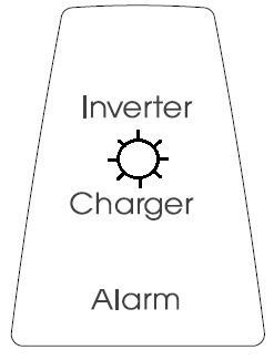 | On / Off / Charger-only switch = Charger only The AC input is switched through, and the charger operates in float or storage mode. |
Note: The inverter/charger will shut down if four abnormal events occur within 30 seconds. It can be reset by switching to Off and then to On again.
For the latest and most up-to-date information about the blink codes, please refer to the Victron Toolkit app. Scan the QR code or click on the below link to go to the Victron software downloads webpage. https://www.victronenergy.com/support-and-downloads/software |  |
Remote control is possible with a 3-position switch or with a Digital Multi Control panel. The control panel has a simple rotary knob with which the maximum current of the AC input can be set: see PowerControl in the General chapter. For the appropriate DIP switch settings, refer to the Configuration by DIP switches chapter.
The Multi does not require specific maintenance. It will suffice to check all connections once a year. Avoid moisture and oil/soot/vapours and keep the device clean.