MultiPlus | 12/500/20 - 120V | 12/800/35 - 120V | 12/1200/50 - 120V | ||
|---|---|---|---|---|---|
PowerControl / PowerAssist | Yes / Yes | ||||
Transfer switch | 16A | ||||
INVERTER | |||||
DC Input voltage range | 9.5 - 17V | ||||
AC output voltage | 120V ±2% | ||||
AC output frequency | 60Hz ±0.1% | ||||
Cont. output power at 25°C (77°F) (2) | 500VA | 800VA | 1200VA | ||
Cont. output power at 25°C (77°F) | 430W | 700W | 1000W | ||
Cont. output power at 40°C (104°F) | 400W | 650W | 900W | ||
Cont. output power at 65°C (149°F) | 300W | 400W | 600W | ||
Peak power | 900W | 1600W | 2400W | ||
Maximum efficiency | 90% | 92% | 93% | ||
Zero-load power | 6W | 7W | 10W | ||
Zero-load power search mode | 2W | 2W | 3W | ||
CHARGER | |||||
AC Input voltage range | 95 - 140V | ||||
AC input frequency range | 55 - 65Hz | ||||
Charge voltage 'absorption' | 14.4V | ||||
Charge voltage 'float' | 13.8V | ||||
Charge voltage 'storage' | 13.2V | ||||
Charge current house battery (3) | 20A | 35A | 50A | ||
Charge current starter battery | 1A | ||||
Battery temperature sensor | Yes | ||||
GENERAL | |||||
Programmable relay (4) | Yes | ||||
Protection (1) | a – g | ||||
Operating temperature | -40 to +65°C (-40 to + 140°F), fan assisted cooling | ||||
Humidity | Maximum 95%, non-condensing | ||||
ENCLOSURE | |||||
Material & colour | Steel/ABS, blue RAL 5012 | ||||
Protection category | IP 21 | ||||
Battery-connection | 16mm² | 25mm² | 35mm² | ||
230V AC-connection | G-ST18i connector | ||||
Weight | 4.4kg | 6.4kg | 8.2kg | ||
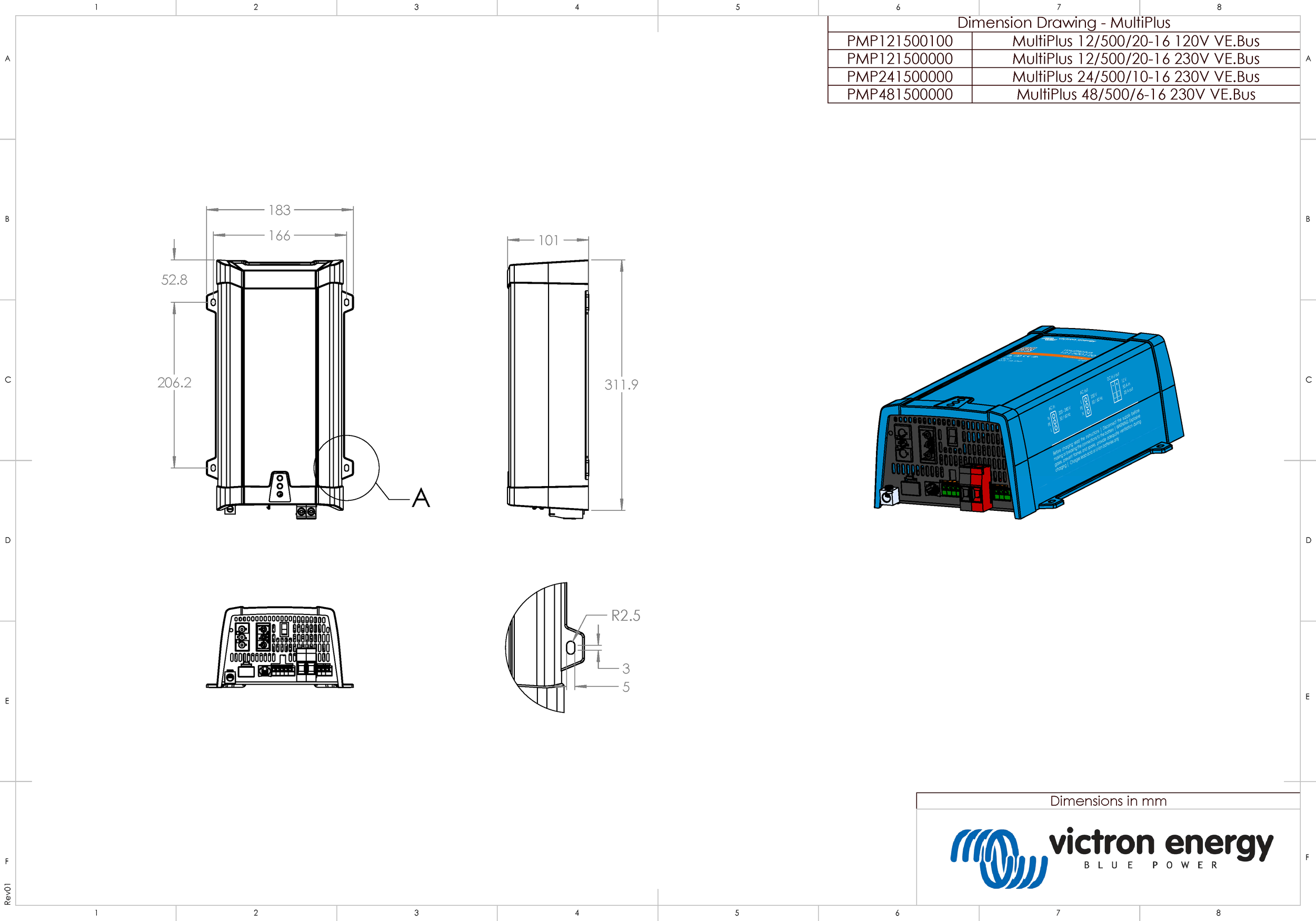
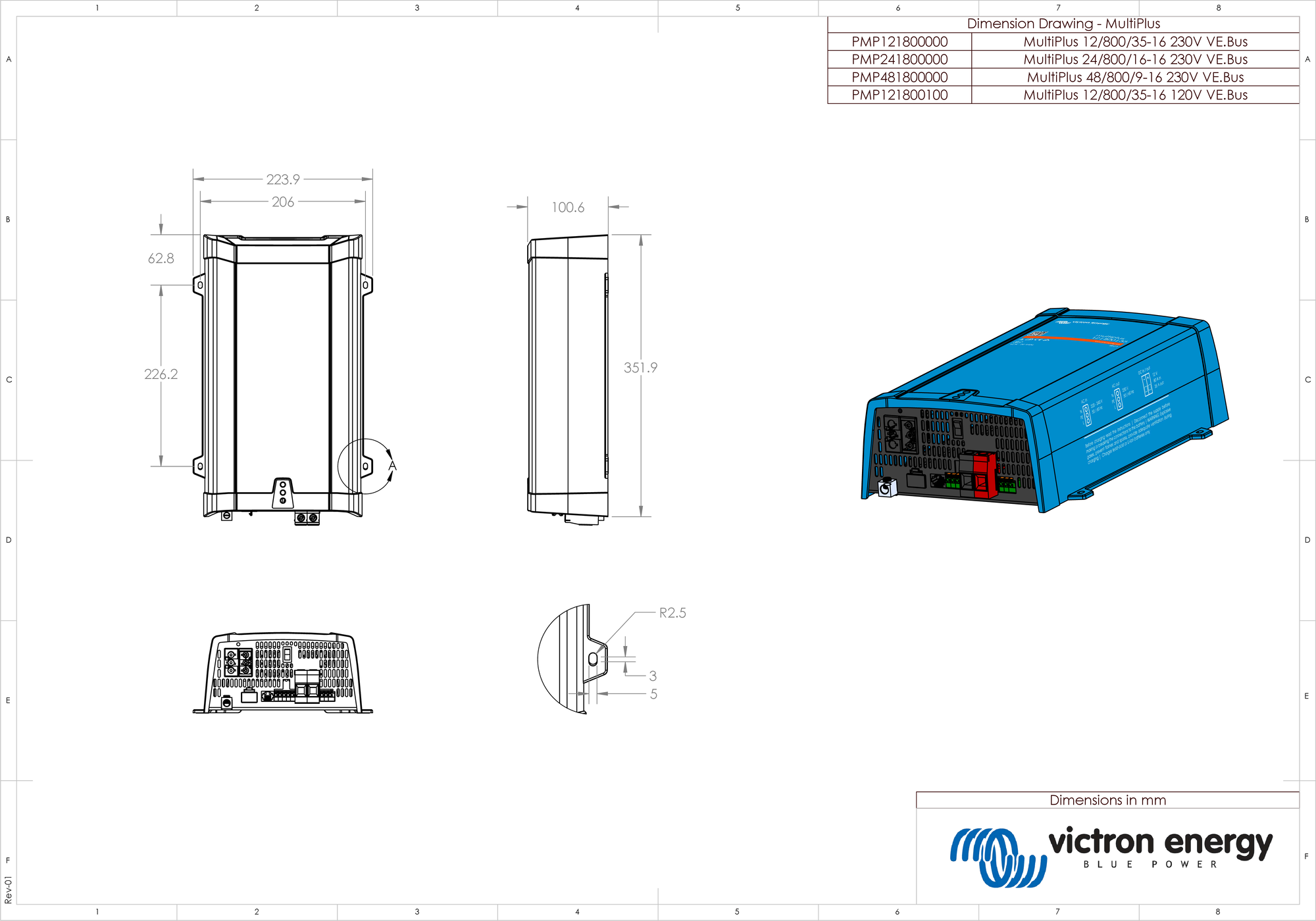
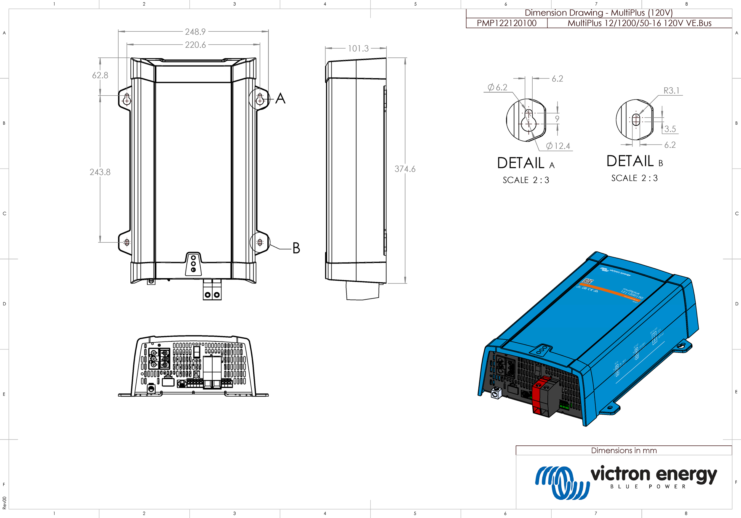
Dimensions (h x w x d) | 311 x 182 x 100 mm | 360 x 240 x 100 | 406 x 250 x 100 mm | ||
STANDARDS | |||||
Safety | EN-IEC 60335-1, EN-IEC 60335-2-29, EN 62109-1 | ||||
Emission / Immunity | EN 55014-1, EN 55014-2, EN-IEC 61000-3-2, EN-IEC 61000-3-3 IEC 61000-6-1, IEC 61000-6-2, IEC 61000-6-3 | ||||
Road vehicles | ECE R10-4 | ||||
| |||||
ID | Description |
|---|---|
A | DIP switches (remove plastic cover) |
B | On/off/charger only switch |
C | VE.Bus communication port |
D | Temperature sensor terminal |
E | Programmable relay terminal |
F | Battery negative connection |
G | Starter battery positive connection |
H | Remote control terminal |
I | AC input terminal (N, PE, L1) |
J | AC output terminal (N, PE, L1) |
K | Battery positive |
L | Earth connection |
ID | Description |
|---|---|
D | AC input (L, N, PE). |
E | AC output (L, N, PE). |
F | Ground AC input and AC output are connected to chassis. |
G | Back feed safety relay. |
H | Ground relay (closed when the back feed relay is open). |
I | DC fuse. |
J | Bidirectional converter. |
K | Chassis on input/output ground terminals should be permanently connected to ground. |
charge stage | Description |
|---|---|
Bulk | Entered when charger is started. Constant current is applied until the gassing voltage is reached (14,4 V resp. 28.8V, temperature compensated). |
Battery safe | If, in order to quickly charge a battery, a high charge current in combination with a high absorption voltage has been chosen, the Multi will prevent damage due to excessive gassing by automatically limiting the rate of voltage increase once the gassing voltage has been reached. The Battery Safe period is part of the calculated absorption time. |
Absorption | A constant voltage period to fully charge the battery. The absorption time is equal to 20x bulk time or the set maximum absorption time, whichever comes first. |
Float | Float voltage is applied to keep the battery fully charged and to protect it against self-discharge. |
Storage | After one day of Float charge the charger switches to storage. This is 13,2 V resp. 26,4 V (for 12 V and 24 V charger). This will limit water loss to a minimum. After an adjustable time (default = 7 days) the charger will enter Repeated Absorption for an adjustable time (default = 1 hour). |
Default output voltages for Float and Absorption are at 25 °C.
Reduced Float voltage follows Float voltage and Raised Absorption voltage follows Absorption voltage.
In adjust mode temperature compensation does not apply.
MultiPlus 12/500/20 - 120V

MultiPlus 12/800/35 - 120V

MultiPlus 12/1200/50 - 120V
