The inverter can be turned on via these methods:
ON/OFF/CHARGER-ONLY switch.
The VictronConnect app.
Remote terminal with wire loop.
Remote switch connected to the remote terminal (optional).
Phoenix Inverter Control VE.Direct panel connected to the remote terminal (optional).
A GX device and the VRM portal (optional).
The inverter can be switched to ECO mode, via the VictronConnect app.
When the inverter is running in ECO mode it reduces power consumption in no-load (standby) operation. The inverter will automatically switch off as soon as it detects that there is no load connected. It then switches on, briefly, every 3 seconds to detect a load. If the output power exceeds the set level, the inverter will continue to operate.
For more information about ECO mode, see the ECO mode and ECO settings chapter.
The solar charger is active as soon as the switch is switched to ON or to CHARGE. The solar charger will start charging the batteries as soon as the solar panel voltage is higher than the battery charger voltage.
The charge algorithm is a 3-stage charge algorithm, similar to that in our other chargers and solar chargers:
Bulk charge stage
The battery is charged at maximum charge current until the voltage increases to the configured absorption voltage. The bulk stage duration is dependent on the battery’s level of discharge, the battery capacity and the charge current. Once the bulk stage is complete, the battery will be approximately 80% charged (or >95% for lithium batteries) and may be returned into service if required.
Absorption charge stage
The battery is charged at the configured absorption voltage, with the charge current slowly decreasing as the battery approaches full charge. The absorption stage duration is adaptive and intelligently varied depending on the battery’s level of discharge – this is determined from the duration of the bulk charge stage. The absorption stage duration can vary between a minimum of 30 minutes, up to a maximum limit of 8 hours (or as configured) for a deeply discharged battery.
Float charge stage
The battery voltage is maintained at the configured float voltage. Once float stage is commenced, the battery is fully charged and ready for use. If the battery is unused, the charger can remain connected to the battery and the float stage will prevent discharge due to the battery's self-discharge.
The inverter can be switched to CHARGE mode via its "ON/OFF/CHARGE" switch.
When in CHARGE mode, the inverter is turned off and only the solar charger is operational. This mode ensures that the battery remains charged from solar power, while AC loads can not discharge the battery, providing the solar panel voltage is higher than the battery voltage.
Use this mode, for example, when the AC loads are not in use or when the installation is not attended.
 |
LEDs | LED behaviour | Operational mode | Troubleshooting |
|---|---|---|---|
 | Green POWER LED off. Red ALARM LED off. | The inverter has been switched off, either directly or via its remote on/off connector, or the inverter is not powered. | Check the ON/OFF/ECO switch: it should be in ON position or in ECO position. To check if the inverter is operational, turn the switch to OFF and then to ON. If not operational, check the following:
|
 | Green POWER LED on. Red ALARM LED off. | The inverter has been switched on and is operational. | n/a |
 | Green POWER LED blinking slow with a short pulse. Red ALARM LED off. | The inverter has been switched to ECO mode and is in "search" state. In other words, the inverter load is lower than the "Wake up power" setting. the inverter sends a search pulse at regular intervals to check if a load has been connected or has been turned on. | If the inverter keeps switching on and off while there is a load connected, the load may be too small compared to the actual ECO mode settings. Either increase the load or change the "wake up power" setting. |
 | Green POWER LED on. Red ALARM LED on. | Overload warning. The inverter is indicating that the AC load is larger than the inverter rating and that if this situation continues, the inverter will switch off due to an overload alarm | Reduce the AC load |
 | Green POWER LED blinking with a fast double pulse. Red ALARM LED on. | Overload alarm. The inverter has shut down due to prolonged overload and will no longer automatically restart. | Remove the cause of the overload and then restart the inverter by switching it off and then back on again. For more information also see the Protections and automatic restarts chapter. |
 | Green POWER LED on. Red ALARM LED blinking slow. | Low battery voltage warning. The battery voltage has dropped below the "Low battery alarm" voltage. Should the battery voltage drop any further, the inverter will switch off on a "Low battery voltage alarm". | Charge the battery and/or turn AC loads off. Also check if all battery cable connections have been tightened. Do the battery cables have a sufficient thickness, is the battery full and is the battery still in good working order? |
 | Green POWER LED on. RED ALARM LED blinking fast. | High Battery voltage warning. The battery voltage is too high. Should the battery voltage increase any further, the inverter will switch off on a "High battery voltage alarm". | Reduce the DC input voltage, check if the battery voltage is correct and if the battery bank is wired correctly. Also check if there perhaps are faulty or incorrect chargers or equipment with a faulty charge regulator. |
 | Green POWER LED on. Red ALARM LED blinking with a fast double pulse. | High temperature warning. The internal temperature is too high. If the temperature increases any further, the inverter will switch off on a "High temperature alarm". | Reduce the AC load and/or move the inverter to a better ventilated area. |
 | Green POWER LED on. Red ALARM LED blinking with a fast single pulse at longer intervals. | High DC ripple warning. The DC voltage has a too high ripple voltage. If the ripple voltage increases any further, the inverter will switch off on a "High DC ripple alarm". | Check if all battery cable connections have been tightened. Do the battery cables have a sufficient thickness? DC ripple is related to a voltage drop over the battery cables. For more information on DC ripple and how to prevent it, see the Wiring Unlimited book. |
 | Green POWER LED blinking with a fast double pulse. Red ALARM LED blinking slow. | Low battery voltage alarm. The inverter has shut down due to low battery voltage. | To restart the inverter, charge the battery or switch the inverter off and then back on again. Check the battery voltage at the battery terminals of the inverter. Also check the DC fuses, cables, and cable connections For more information also see the Protections and automatic restarts chapter. |
 | Green POWER LED blinking with a fast double pulse. RED ALARM LED blinking fast. | High battery voltage alarm. The inverter has shut down due to high battery voltage. | Reduce the DC input voltage, check if the battery voltage is correct and if the battery bank is wired correctly. Also check if there perhaps are faulty or incorrect chargers or equipment with a faulty charge regulator. The inverter will automatically turn back on when the battery voltage has dropped to an acceptable level. For more information also see the Protections and automatic restarts chapter. |
 | Green POWER LED blinking with a fast double pulse. Red ALARM LED blinking with a fast double pulse. | High temperature alarm. The inverter has shut down due to high temperature. | Wait until the inverter has cooled down. The inverter will automatically turn back on when its internal temperature has dropped to an acceptable level. Check the environment of the inverter, can the ventilation be improved, or can the inverter be moved to a cooler location? For more information also see the Protections and automatic restarts chapter. |
 | Green POWER LED blinking with a fast double pulse. Red ALARM LED blinking with a fast single pulse at longer intervals. | DC ripple alarm. The inverter has shut down due to high DC ripple. | Check if all battery cable connections have been tightened. Do the battery cables have a sufficient thickness? DC ripple is related to a voltage drop over the battery cables. For more information on DC ripple and how to prevent it, see the Wiring Unlimited book. To restart the inverter switch the inverter off and then back on again. For more information also see the Protections and automatic restarts chapter. |
 | Green POWER LED and red ALARM LED blinking fast in an alternating fashion. | Firmware update active. | Wait until the update has been finalized. If the firmware update fails retry the firmware update. |
 | Green POWER LED and red ALARM LED blinking slow in an alternating fashion. | Calibration or parameter error. | Contact your Victron supplier for support. |
The yellow STATE LED indicates the state of the solar charger. This LED operates independently from the POWER LED and the ALARM LED.
 |
LED | LED behaviour | Operational mode | Battery |
|---|---|---|---|
 | Yellow STATE LED off. | The solar charger is switched off, or there is not enough solar power to charge the battery. | The battery is not being charged by the SUN inverter. |
 | Yellow STATE LED blinking fast. | The solar charger is charging the battery and is in the bulk stage*. | This is the first part of the charge cycle. The battery has a state of charge between 0% and 80%. |
 | Yellow STATE LED blinking slow. | The solar charger is charging the battery and is in the absorption stage*. | This is the second part of the charge cycle. The battery has a state of charge between 80% and 100%. |
 | Yellow STATE LED on. | The solar charger is charging the battery and is in the float stage*. | This is the final part of the charge cycle. The battery is full. The charge voltage has been reduced. |
*) For an explanation of the charging algorithm, see the Solar charger chapter. | |||
Overload
Some loads like motors or pumps draw large inrush currents in a start-up situation. In such circumstances, it is possible that the start-up current exceeds the over current trip level of the inverter. In this case the AC output voltage will quickly decrease to limit the output current of the inverter. If the over current trip level is continuously exceeded, the inverter will shut down, wait 30 seconds and then restart.
After 3 restarts, followed by another overload within 30 seconds of restarting, the inverter will shutdown and remain off. The LEDs will signal shutdown due to overload. To restart the inverter, switch it off and than back on again.
Low battery voltage (adjustable)
The inverter will shut down when the DC input voltage drops below the "Low battery shutdown" parameter. The LEDs will signal shutdown due to low battery. The inverter will automatically restart, after a minimum delay of 30 seconds, when the battery voltage has increased above the "Low battery restart" parameter.
After three restarts, followed by another low battery shutdown within 30 seconds of restarting, the inverter will shutdown and remain off. The LEDs will signal shutdown due to low battery. To restart the inverter, switch it off, and then on again. Alternatively, recharge the battery. The inverter will automatically restart when the battery voltage has increased for at least 30 seconds above the "Charge detect" parameter.
See the Technical specifications chapter for default low battery shutdown and restart levels. The levels can be customized via the VictronConnect app.
Alternatively, a dynamic low battery cut off can be implemented. For more information, see the Dynamic cut off chapter.
High battery voltage
The inverter will shut down when the DC input voltage is too high. The LEDs will signal shutdown due to high battery. The inverter will first wait 30 seconds and will only resume operation once the battery voltage has dropped to an acceptable level.
Check for faulty battery chargers, alternators or solar chargers connected to the battery.
High temperature
The inverter will shut down if it detects a too high internal temperature. The LEDs will signal shutdown due to high temperature. The inverter will wait 30 seconds and will only resume operation when the temperature has dropped to an acceptable level.
High temperature alarms are generally caused by a too high ambient temperature, often in combination with a high inverter load. Check if the area the inverter is used in, is well ventilated and perhaps even air-conditioned.
High DC ripple
The inverter will shut down if it detects a too high DC ripple. The LEDs will signal shutdown due to high DC ripple. The inverter will wait 30 seconds and then resumes operation again. If after 3 restarts, the DC ripple voltage is still too high, the inverter will shutdown and will not attempt to restart again. To restart the inverter, switch it off and then switch it on again.
High DC ripple is usually caused by loose DC cable connections and/or too thin DC wiring. To clear or prevent ripple alarms, check the wiring between the battery and the inverter. Check if the wiring is the recommended thickness, that all connections are tightened correctly and that the fuses and battery isolators are in good working order. For more information on DC ripple see the Wiring Unlimited book.
Continuous high DC ripple reduces the life expectancy of the inverter.
The VictronConnect app can be used to monitor the inverter.
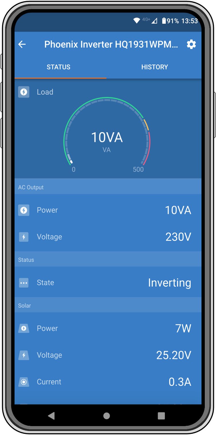 |
VictronConnect app.
For information on how to connect see the The VictronConnect app chapter and/or the VictronConnect manual which can be found on the VictronConnect app information page.
The VictronConnect app will display the following information:
Inverter load as a percentage of the inverter rating.
AC output voltage.
Battery voltage.
Operational state.
Warning or alarm messages *.
Solar power.
Solar voltage.
Solar current **.
Solar open circuit voltage **.
*) Please note that the app is not active in the background. This means that the app will not send alarms or warnings to your phone unless the app is active in the foreground.
**) The "open circuit voltage" is the solar panel voltage when no current is pulled from the panel. In situations where the open circuit voltage is lower than the battery voltage, the solar current cannot be measured and as a result of this, the VictronConnect app will indicate that the open circuit voltage is not available. The same is the case if the solar charger is in the bulk stage or at the beginning of the absorption stage. The reason is that all solar power goes into the battery and the open solar voltage effectively becomes the battery voltage. Only during a charge stage like at the end of absorption or float stage, where only little current is required, the hardware can measure the "open circuit voltage".
The inverter can be connected to a GX device, like a Cerbo GX or a Color Control GX. When connected the GX device will display the inverter on the system overview screen and the device list. The GX device will also display a message in case of an inverter warning or alarm.
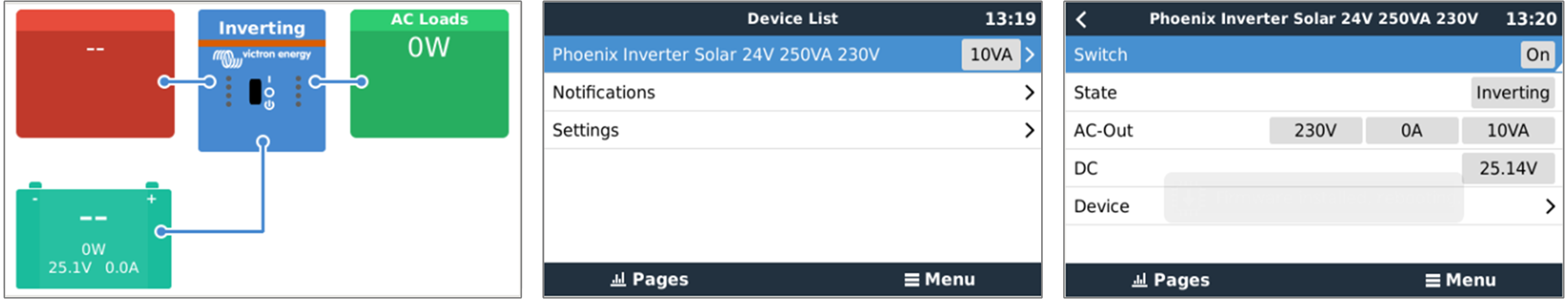
Example of GX screens from left to right: system screen, device list and inverter device screen.
If the GX device is connected to the internet, the inverter can be remotely monitored via the VRM portal. For more information on the VRM portal, see the VRM - Remote monitoring information page.
Alternatively, the inverter can be connected to a GlobalLink 520, and then remotely monitored via the VRM portal.