Equipment in modern systems needs to be able to communicate, either with each other or with a control or monitoring device. To make communication happen, communication cables are required. They send information from one piece of equipment to another piece of equipment. Quite often, these are mission-essential communications. If the cable fails, the communication stops, and the system might stop operating. |
Some examples of communication cables used in inverter/charger systems:
|
A data signal is a signal that constantly changes in line with the information it sends. It can be analogue or digital. The signals in communication cables can be any of these types. These signals have a low voltage and current. Often no more than 5V. |
The different signal types: | ||
| The voltage can have any value, and there is a direct correlation between voltage and value. | 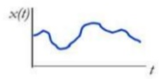 |
| The voltage of the signal is limited to a finite set of voltages. | 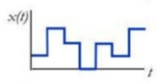 |
| There are only two voltage values. The signal represents an on/off condition or is used to transmit data by sending strings of ones and zeros. | 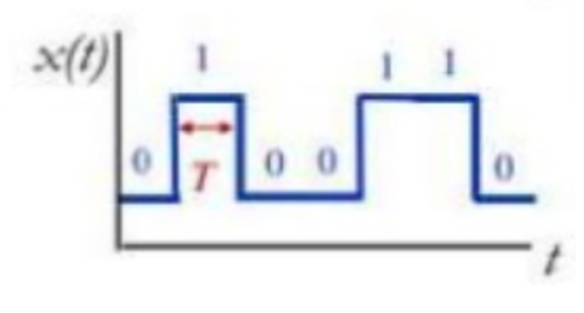 |
Like with all cabling, it is important that the communication cables are of good quality. Also, their connectors need to be of good quality and that they have been crimped on the cable correctly. It also matters how good the connection to the receiving socket is. Communication cables carry low voltage signals of low current. If these signals travel over a distance, of course, a voltage drop can occur, but that is not so common, because these signals only carry a very low current. A voltage drop will not normally be an issue unless the cables are very long. However, another aspect is critical for communication cables when low voltage signals are sent over a long distance and that is interference. |
The different interference types and what they are caused by:
In the first 4 cases, the cable acts as an antenna and it receives this interference. The interference induces additional electricity into the communication cables. This will change the voltage of the signal resulting in an alteration of the data that is being sent and will cause confusing or disrupted communication. In really bad cases, where there is a lot of interference or a grounding issue, the voltages in the cable can become so high that it causes damage to the communication circuitry in the equipment that connects to the communication cable. |
There are ways to limit or prevent interference, these are:
|
Unshielded and untwisted cables: These cables are very susceptible to interference. And because of this, they have a length limit. This is approximately 10 meters. This is why we do not sell VE.Direct cables longer than 10 meters. The VE.Direct cable is unshielded and untwisted cable. |  Unshielded untwisted. | |
Twisted pair cables: Two conductors of a single circuit are twisted together. This will improve the rejection of electromagnetic interference and it also will make the cable less susceptible to cross-talk from neighbouring cables. | 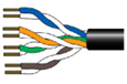 Unshielded twisted pair. | |
Cable shielding: A metal foil or braid covers a group of cables or might even cover twisted pairs. | ||
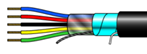 Foil shield |  Braid shield | 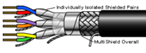 Multi shield |
This paragraph contains a short selection off commonly used communication cable types as used in inverter/charger systems. |
Communication cable types: | |
RJ45 straight UTP cable: This cable is used for computer networks, internet, and ethernet, but they are also used for inverter/chargers to communicate to each other and to a control product, like the Multi Control panel or a GX device. This cable has 8 conductors. In a straight cable pin 1 on one side connects to pin 1 on the other side, pin 2 connects to pin 2 and so on. To test if the cable is wired correctly use a cable tester. Victron uses this cable for VE.Bus and VE.Can products. It was also used for the, now deprecated, VE.Net products. In the past, these cables usually had a blue colour, but more different colour cables have recently appeared. Victron manufactures different length cables as do other manufacturers. For more information see: https://www.victronenergy.com/cables/rj45-utp-cable. It is not recommended to make these cables yourself. A badly crimped connector can be the cause of hard-to-diagnose system faults. To test an RJ45 cable, first, replace the cable and see if the problem has gone away. Another source of faults is when the male RJ45 connector is not properly inserted into the female RJ45 socket or when the RJ45 sockets contacts have lost their springiness and do not make good contact anymore. ImportantBe aware of RJ45 cross-over cables. They look like a regular “straight” RJ45 UTP cable. These were used in old computer networks or used by other inverter manufacturers. It can be very off-putting in case one of these cables are used where a straight cable should have been used. These cables cannot be used for Victron equipment. Some Victron products have only a single RJ45 connector, in that case use an RJ45 splitter. For more information see: https://www.victronenergy.com/cables/rj45-splitter. | 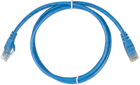 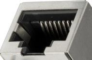 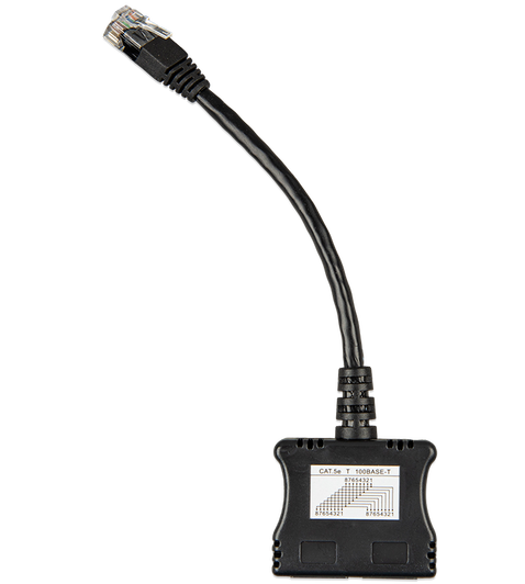 |
RJ45 Terminator: Used to terminate a daisy chain CANbus network. One terminator is placed at the first item in the chain and one at the last item in the chain. They ship as a pair, since a VE.Can system always need two terninators. For more information see: https://www.victronenergy.com/accessories/ve-can-rj45-terminator. |  |
RJ45 cable with special pinout: They look like regular “straight” RJ45 UTP cables, but they have been rewired to serve a specific purpose. These types of cables are for special applications. They often only have a unique application. In the case of Victron they are used between a smart battery and a Color Control GX or other GX device. Cable labelling is very important. The label needs to indicate how the cable is internally wired. This means that at a later stage these cables do not end up in a regular system, where they can potentially cause a communication fault. For more information see: https://www.victronenergy.com/cables/ve-can-to-can-bus-bms. | 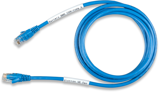 |
RJ12 UTP cable: These are used between the BMV shunt and the BMV head unit. This is a cable with 6 conductors. These cables are normally used to send digital data but the BMV uses it to send analogue data. The BMV is supplied with one of these cables. Victron manufactures cables of various lengths, choose one of these if a bespoke cable is needed. As with the RJ45 cable, only use pre-manufactured cables. We do not recommend that you make this cable yourself. Too often a badly crimped connector is the cause of a hard to diagnose strange system behaviour. Cables with RJ12 connectors are also commonly used for telephones. But in case of a telephone cable not all 6 wires are present. Also, the phone cable is not twisted pair. They cannot be used for a BMV. For more information see: https://www.victronenergy.com/cables/rj12-utp-cable. | 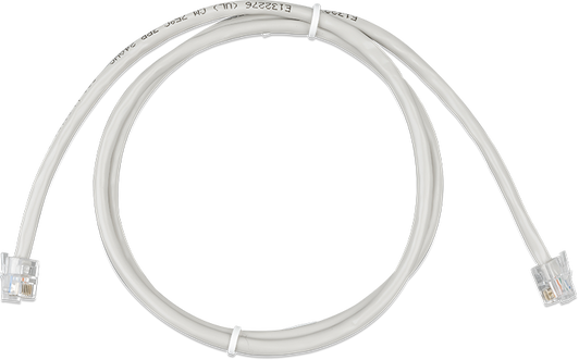 |
VE.Direct cable: This is 4 core data cable. This is a special cable for monitoring or control of certain Victron products like a BMV or MPPT. For more information see: https://www.victronenergy.com/cables/ve.direct.cable. | 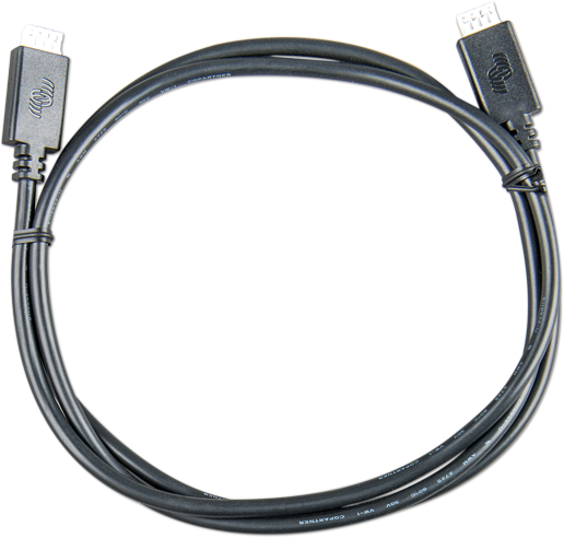 |
Signal or hook-up wire: This is mostly a thin wire, usually no thicker than 1.5mm2. They come as cable in a variety of colours and with single, double or multiple conductors. These cables typically carry low current analogue signals or on/off signals. For marine applications use hook-up wire with tinned copper strands. | 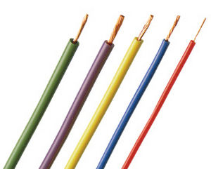 |
NMEA2000 cables and connectors: Used in marine CAN-bus data networks. This cabling consists of special marinized data cable and waterproof connectors, T pieces and terminators. For more information see Wikipedia. | 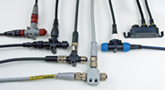 |
RS485 cables: Used for serial communications. In the case of Victron, it is used for communication between energy meters and a GX device. For more information on RS485 see Wikipedia. | 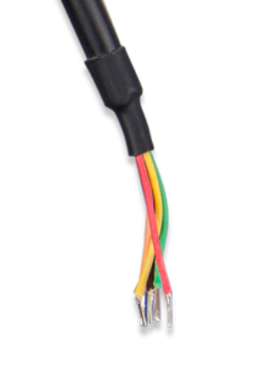 |
USB cables: Available in a variety of types. Victron mainly uses the type A connector. For more info on USB see Wikipedia. | 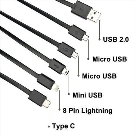 |
Interfaces are small devices that translate one data protocol to another data protocol. They are often wired into a cable or are located at one end of a cable. |
Some Victron specific interface examples: | |
MK3 to USB interface: It is used to connect a computer to a VE.Bus product. The MK3 had replaced the MK2 interface. The MK2 can still be used, but it is not recommended. Seriously consider upgrading to an MK3. For more information see: https://www.victronenergy.com/accessories/interface-mk3-usb | 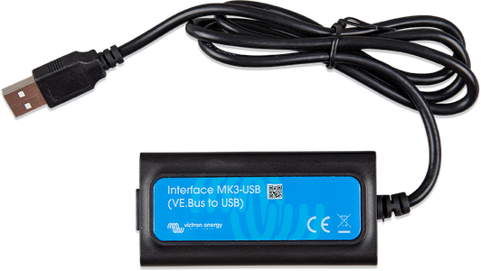 |
VE.Direct to USB interface: It is used to connect a computer to a VE.Direct product or used to connect a VE.Direct product to a GX device USB port. For more information see: https://www.victronenergy.com/accessories/ve-direct-to-usb-interface | 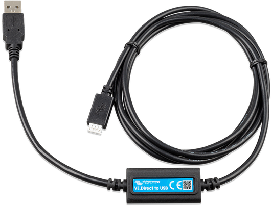 |
RS485 to USB interface: It is used to connect an energy meter to a GX device. For more information see: https://www.victronenergy.com/accessories/rs485-to-usb-interface | 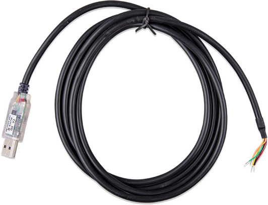 |
VE.Can to NMEA 2000 micro-C male cable: It is used to connect a VE.Can product to an NMEA 2000 network. https://www.victronenergy.com/accessories/ve-can-to-nmea2000-micro-c-male | 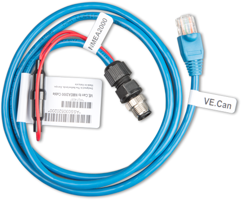 |
For the full range of Victron interfaces, see the Victron accessories product page at: https://www.victronenergy.com/accessories.