Warning
WARNING: Make sure that all AC power sources are switched off or disconnected before and during installation.
Mounting:
Install the transfer switch in a dry and well-ventilated area.
To gain access to the transfer switch, remove the four screws in the front panel.
The transfer switch can be wall-mounted by using the four holes in the rear of the casing.
Electrical connections:
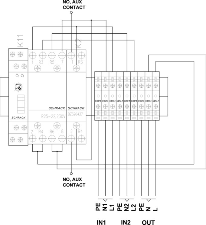
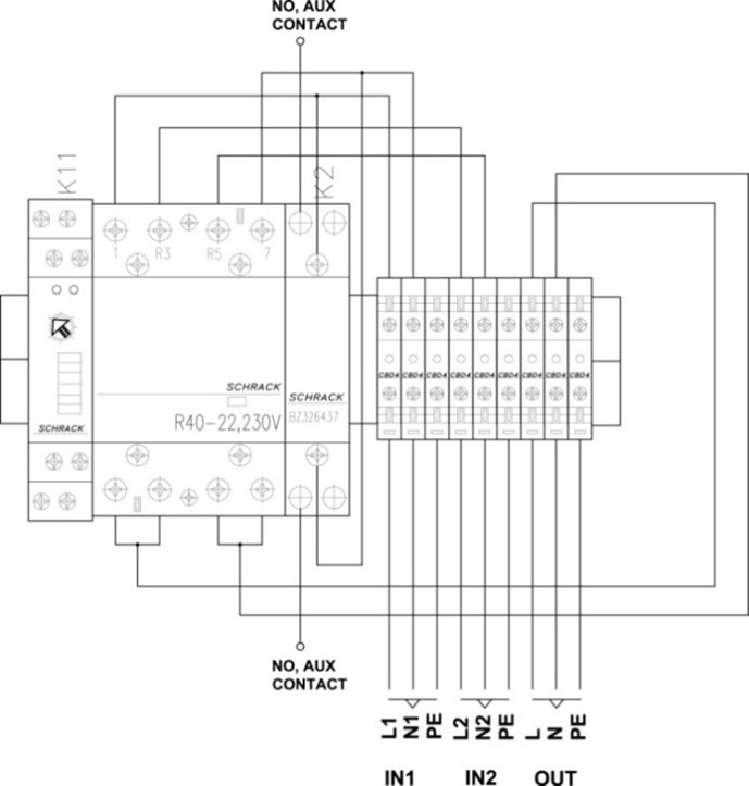
The input cables (mains/generator) and the inverter (or inverter/charger) and the output cable (to the appliances) should be connected according to the connection diagram as shown below.
The input and output cables must have the correct core thickness for a safe installation. Undersized cables can cause overheating of the cables. The maximum cable core thickness is 6mm².
Use the provided cable glands to pass the input and output cables through the casing.
Tighten all connections with a nominal torque moment of 1.2Nm. This is to limit transition resistance as far as possible. Loose connections can cause dangerous overheating of the terminals.
 Connection diagram VE Transfer Switch 5kVA. |  Connection diagram VE Transfer Switch 10kVA. |
Digital Multi Control panel connection:
When the transfer switch is used together with a MultiPlus and a Digital Multi Control panel (DMC):
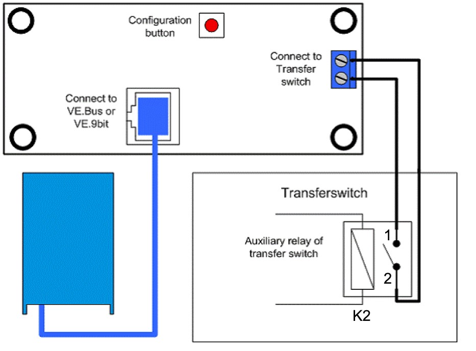
Connect the transfer switch Auxiliary contact 1 and 2 of relay K2 (NO) to the screw connector on the back of the DMC as indicated in the connection diagram below.
When the transfer switch auxiliary contact is open, the MultiPlus current limit is controlled by the knob on the front of the DMC. The display on the DMC will show the current limit value.
When the transfer switch auxiliary contact is closed, a pre-set (generator) current limit is sent to the MultiPlus. The display on the DMC will show the text: "GEN".
For more information on this feature and on how to set the preset (generator) current limit see the Digital Multi Control Panel manual.
 |
Connection diagram Digital Multi Control panel.
Fusing, earth leakage protection and grounding:
The AC input and output wiring must be protected by fuses or miniature circuit breakers (MCBs) that are suitable for the system's wire cross-section.
External earth leakage switches (RCDs or RCCBs) must be integrated with the transfer switch wiring.
All ground connections of the power sources and power consumers must be connected to the central ground connection of the ship or the electric installation.
Configuration:
In most cases, there is no need to configure the transfer switch. The transfer switch is ready for use straight after installation. However, in some specific circumstances, an adjustment of the "switch on delay" of input 1 is needed. Make the delay time adjustment using a small flat-blade screwdriver.