What is ESS?
An Energy Storage System (ESS) is a specific type of power system that integrates a power grid connection with a Victron Inverter/Charger, GX device and battery system. It stores solar energy in your battery during the day for use later on when the sun stops shining.
It allows for time-shifting power, charging from solar, providing grid support, and exporting power back to the grid.
When an ESS system is able to produce more power than it can use and store, it can sell the surplus to the grid, and when it has insufficient energy or power, it automatically buys it from the grid.
What is the minimum requirement for ESS?
There must be at least one inverter/charger (MultiPlus/Quattro) and one GX device such as the Cerbo GX or Ekrano GX in the system.
Other components can be added when needed; see the ESS system design chapter.
Note: The information contained in this ESS manual does not apply to the Multi RS models, which use a VE.Can interface (not VE.Bus); see the RS product manuals for specific information on programming them for ESS.
When is it appropriate to use ESS?
Use ESS in a self-consumption system, a backup system with solar, or a mixture of both. For example, you can use 30% of the battery capacity for self-consumption and keep the remaining 70% available as a backup in the event of a utility grid failure.
ESS can be configured to optimise self-consumption or to keep batteries charged.
Optimising self-consumption:
When there is more PV power than is required to run loads, the excess PV energy is stored in the battery. That stored energy is then used to power the loads at times when there is a shortage of PV power.
The percentage of battery capacity used for self-consumption is configurable. When utility grid failures are extremely rare, it could be set to 100%. In locations where grid failure is common, or even a daily occurrence, such as in some African countries, you might choose to use just 20% of battery capacity and save 80% for the next grid failure.
Keep batteries 100% charged:
ESS can also be configured to keep the batteries fully charged. A utility grid failure is then the only time battery power is used as a backup. Once the grid is restored, the batteries will be recharged either from the grid or from solar panels when available.
ESS in a system with a generator
Configuring ESS in a system that uses a diesel generator as a backup for extended mains failures is also possible. Grid code and loss of mains (LOM) configuration will need special attention; see the VEConfigure: grid codes & loss of mains detection documentation.
On the GX device, select 'Generator' as the AC Input type in the Settings → System setup menu. The system will then enable generator charging, ensure that the generator is properly loaded, and will be automatically shut down as soon as parameters are met.
When not to use ESS
In off-grid systems, with or without a generator
In marine systems
In automotive systems
Inverter priority, also known as 'Intentional islanding“ or 'Ignore AC' input systems
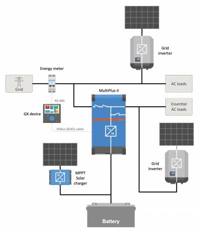
ESS with and without grid meter
ESS can be used with or without an external grid meter.
Where there is a grid meter, either a full or partial grid-parallel system can be configured to run alongside.
Where there is no grid meter, all loads are connected to AC-out. This also applies to a PV Inverter that is also connected to AC-out.

Optional feed-in of MPPT solar charger power
Power from an MPPT can be fed back to the grid, enabled/disabled by a user setting on the GX device in Settings → ESS.
Fronius Zero feed-in option
By using the "Power Reduction" feature in Fronius grid-tie inverters, the ESS system can automatically reduce the output of the installed PV inverters as soon as feed-back is detected; without switching and frequency shifting.
It is not possible to combine ESS with the Fronius Smart Meter, but it's not necessary either, as ESS already has metering.
With ESS, it is not possible to disable feed-in a system with other brands of grid-tie inverters. See the Feed-in or no feed-in section for more information.
ESS Training
Energy Storage System introduction, examples and diagrams
A separate document that provides further introductory information, overviews, and system examples is available to download here.
Advanced control options
A separate document that provides further information on ESS mode 2 and 3 as advanced control option See is available to download here.
Residential scale Energy Storage System with MPPT Solar Charger
Retrofitting an existing Grid-tie inverter installation
System with Generator backup (using the generator auto start/stop feature in the GX device)
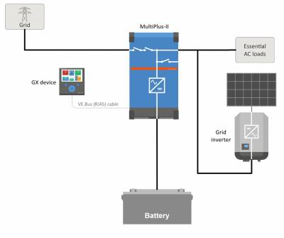
Backup system with Solar
All loads are wired on the AC output of the inverter/charger. The ESS mode is configured to 'Keep batteries charged'.
When using a grid-tie inverter, it is connected to the AC output as well.
When grid power is available, the battery will be charged with power from both the grid and the PV. Loads are powered from PV when that power source is available.
Feed-in is optional and can be enabled or disabled depending on local regulations.
Inverter/charger
The Energy Storage System uses a MultiPlus or Quattro bidirectional inverter/charger as its main component.
Note that ESS can only be installed on VE.Bus model Multis and Quattros which feature the 2nd generation microprocessor (26 or 27). All new VE.Bus Inverter/Chargers currently shipping have 2nd generation chips.
The Multi RS is currently excluded and does not yet support ESS.
GX device
The system is managed by the GX device, which also provides extensive monitoring, both locally and remotely via our VRM Portal and the VRM App.
Battery
Victron Lithium batteries
Third-party battery compatibility
Please see this list of third-party batteries with which Victron equipment is compatible:
Lead batteries: OPzS and OPzV
The relatively high internal resistance of these types of batteries should be considered when designing a system that uses them.
Lead batteries: AGM / GEL
Note that the use of standard AGM and GEL batteries is not recommended for installations designed to cycle the battery bank every day.
Battery Monitor
In most situations, it is not necessary to install a battery monitor:
Lithium batteries with canbus connection (BYD B-Box, Pylon, LG Resu and others) already have a built-in battery monitor. Adding another will only set up a conflict. Always use the canbus connection to provide battery status/state-of-charge data for these batteries.
Redflow ZBM / ZCell zinc-bromide flow batteries with the ZCell BMS also support the same canbus protocol. This is the preferred integration approach for these batteries.
The built-in battery monitor of the Multi Inverter/Charger can be used to provide data where installed batteries do not have a monitor built-in. The advantage here is that in an ESS system the charge currents from MPPT Solar Chargers will also be taken into account.
The only situation where an external battery monitor is required is when a system using a no-monitor battery type also has additional power sources: for example, a DC wind generator. (No monitor battery types include lead batteries, for example, or Victron 12.8V lithium batteries.)
Where an additional battery monitor is necessary, use one of these:
Detailed information is available in the CCGX manual chapter 5.2.
Grid Meter (optional)
An Energy Meter can be installed in the main distribution panel between the grid and the installation for a full or partial grid-parallel installation.
A grid meter is not required where there is no AC renewable-energy source(s) and also no AC load(s) present on the input side of the Multi/Quattro system (i.e. where all such sources and loads are on the output side of the Multi/Quattro system).
If there is any AC renewable energy source or any AC load between the grid connection point and the input side of the Multi/Quattro system, incorrect results will be calculated and recorded by the GX unless a grid meter is installed and enabled.
In particular, without a grid meter:
When renewable energy is being provided on the input side, the grid value will be wrong (too low/negative); and
The AC Load value shown will be too low (and will show zero where there is a surplus of renewable energy).
Both issues are resolved by installing a grid meter.
Click here for more information about the configuration and selection of grid meters.
PV (optional)
ESS can work with both Grid-tie PV inverters and/or MPPT Solar Chargers. (A mix of both is also possible.)
When using Grid-tie PV Inverters we recommend monitoring is performed using the CCGX. See CCGX manual for the options.
ESS can also be operated without PV. This is typical for virtual power plants, where the installation is part of a cluster of small storage systems - supplying energy to the grid during peak demand.