The AC and DC wires into and out of the VE Panel enclosure must be protected as required by code in NA. This can be done by using jacketed wires or by feeding the wires through conduit.
Use proper clamps or other approved methods for securing the cable/conduit to the enclosure.
Do not mix AC and DC wiring in the same conduit. The VE Panel enclosure is specify approved/designed for both AC and DC wiring. However, where DC wiring must cross AC or vice-versa, try to make the wires at the crossing point 90° to one another.
Use only copper wires with a minimum rating of 150V, 75°C if only 120 VAC power is being used; or, with a minimum rating of 300V, 75°C if 120/240 VAC power is being used.
The equipment grounding conductors must be bare (no insulation), or have green or green with yellow-striped insulation or identification. The hot ungrounded conductor (DC positive/AC hot) is usually red or black.
Busbar Torque Values
Small Busbar Screws | 18 - 10 AWG | 6 – 1mm² | 20 Inch Pound | 2.3N-m |
Small Busbar Screws | 8 AWG | 8.36mm² | 25 Inch Pounds | 2.8N-m |
Small Busbar Screws | 6 AWG | 13.3mm² | 35 Inch Pounds | 4N-m |
Large Busbar Screws | 18 - 10 AWG | 6–1mm² | 35 Inch Pounds | 4N-m |
Large Busbar Screws | 8 AWG | 8.36mm² | 40 Inch Pounds | 4.5 N-m |
Large Busbar Screws | 6-4 AWG | 13-21mm² | 45 Inch Pounds | 5 N-m |
Large Busbar Screws | 3-1/0 AWG | 27-54mm² | 50 Inch Pounds | 5.6 N-m |
Breaker Torque
DC DIN Rail Mounted Breakers | 20 Inch Pounds | 2.3 Nm |
AC DIN Rail Mounted Breakers | 20 Inch Pounds | 2.3 Nm |
5A to 100A DC Panel Mounted Breakers | 30 Inch Pounds | 3.4 Nm |
Inverter/3.4 Nm 250A Breaker | 18 Foot Pounds | 24.9 Nm |
Shunt Torque
MidNite Solar PN MNSHUNT 50mV/500amp | 180 Inch Pounds | 20.4 Nm |
Victron PN SHU500050100 Shunt 500A/50mV | 180 Inch Pounds | 20.4 Nm |
Inverter/Charger Torque Requirements
MultiPlus 3k
Battery Stud Terminals | 97 Inch Pounds | 11 Nm |
AC Terminal Blocks | 16 Inch Pounds | 1.6 Nm |
Quattro 5k
Battery Stud Terminals | 124 Inch Pounds | 14 Nm |
AC Terminal Blocks | 62 Inch Pounds | 7 Nm |
Diagrams of the AC and DC wiring for the VE Panel Series enclosure are shown in Figures 8 through 17 and are provided to assist you or your system installer.
Due to the variety of applications and differences in local and national electrical codes, these wiring diagrams should be used as general guidelines only.
They are not intended to override or restrict any national or local electrical codes. The diagrams should not be the determining factor as to whether the installation is compliant, that is the responsibility of the electrician and the on-site inspector.
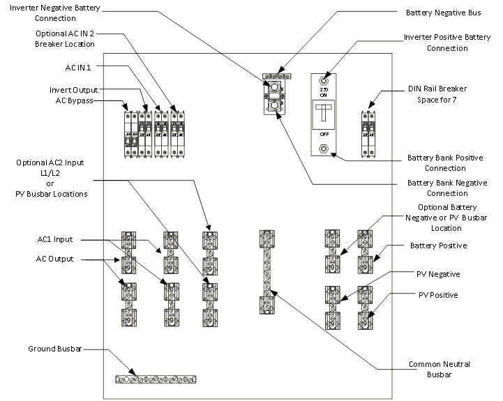 |
Figure 8 - NA 5kVA Component Locator
 |
Figure 9 - NA 3kVA Component Locator
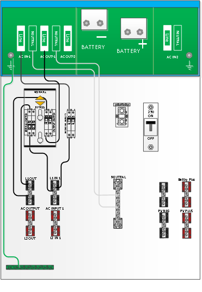
Figure 10 - NA 5kVA Single AC Connection Points
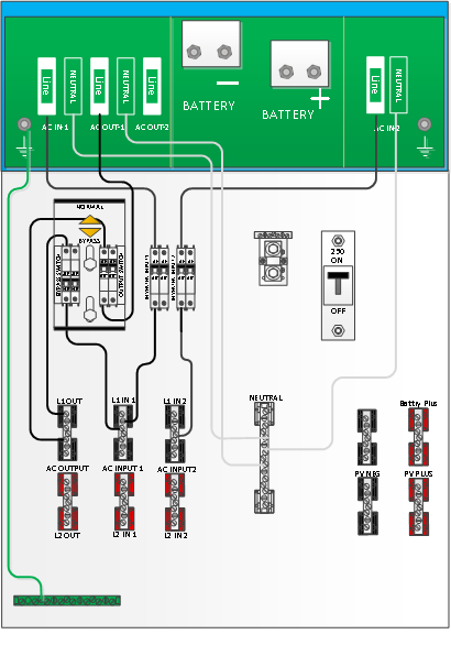
Figure 11 - NA 5kVA Single Optional AC2 IN Connection Points
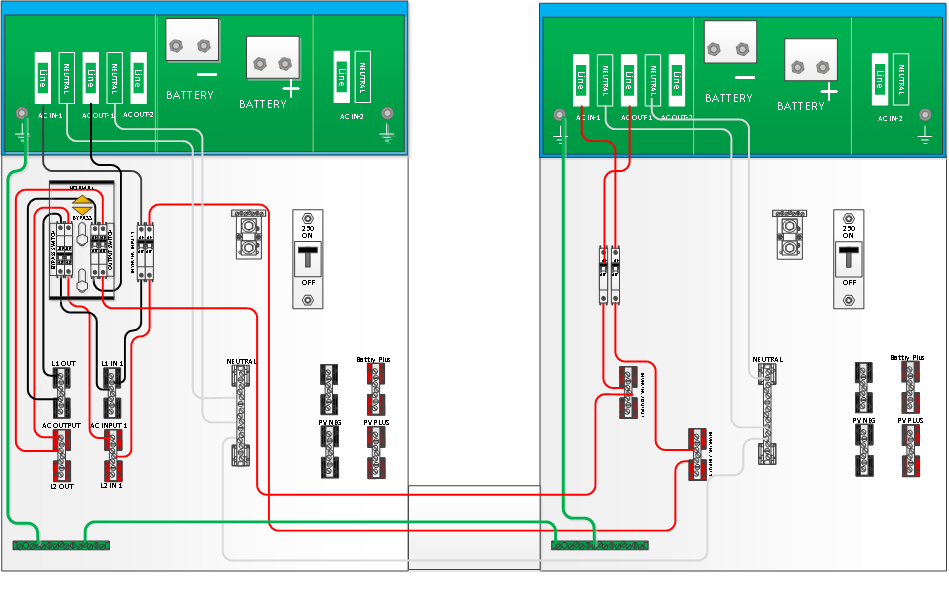
Figure 12 - NA 5kVA Dual Stack AC (1 AC Input) Connection Points

Figure 13 - NA 5kVA Dual Stack AC (2 AC Inputs) Connection Points
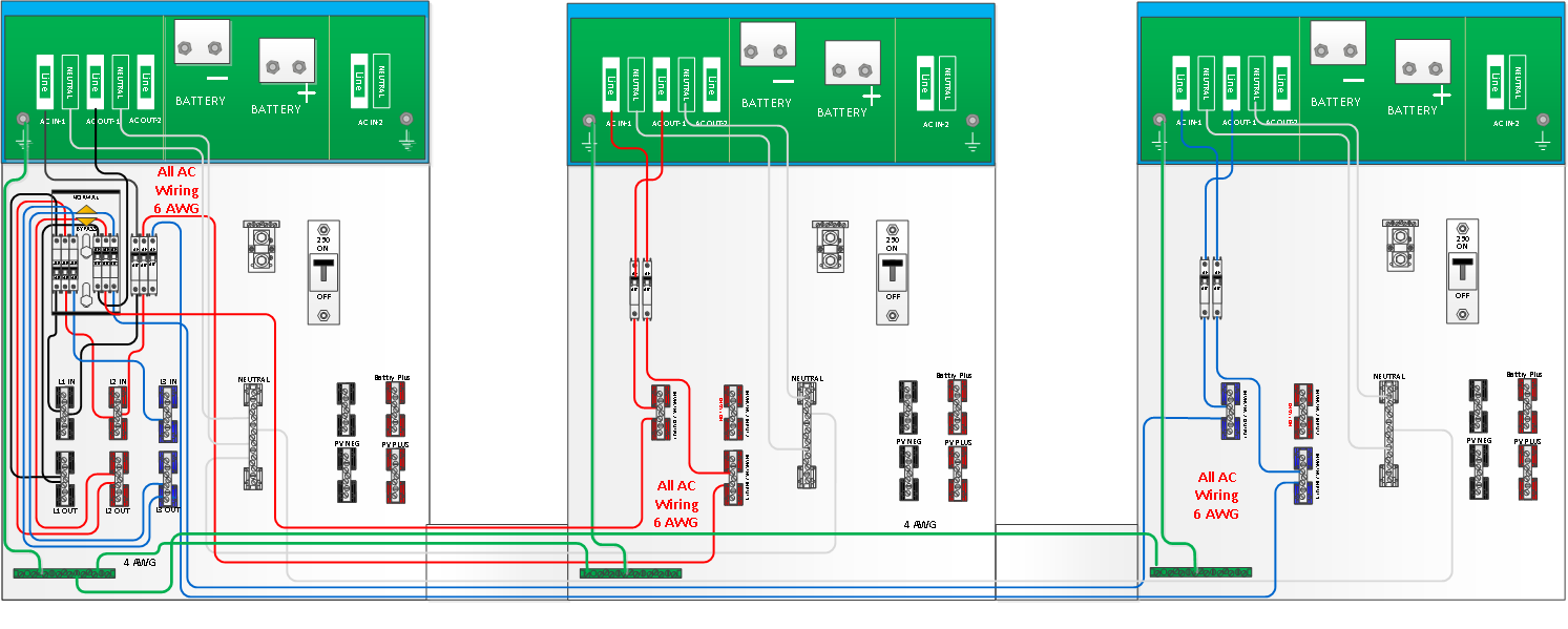
Figure 14 - NA 5kVA 3-Phase AC Connection Points
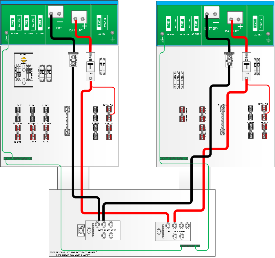
Figure 15 - NA 5kVA Dual Stack VE Panel Battery Connection Points
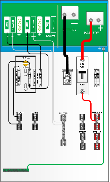
Figure 16 - Export 3kVA Single VE Panel AC and DC Connection Points
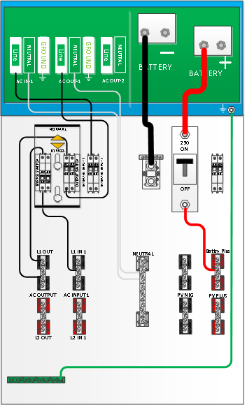
Figure 17 - NA 3kVA Single AC and DC Connection Points
During normal operation, the terminals, busbars, and electrical components inside the VE Panel enclosure may be energized – DO NOT TOUCH. Disconnect all power sources before removing the cover
Even though DC voltage is “low voltage”, significant hazards may be present, particularly from short circuits of the battery system.
Before wiring the DC cables, review the safety information at the beginning of this manual and the following information to ensure a safe and long-lived system.
Failure to use the proper terminal may cause the connection to heat-up, and may eventually fail or become a fire hazard.
DO NOT connect the battery cables to the inverter/charger until all wiring is complete and the correct DC voltage and polarity have been verified.
When the inverter/charger is installed in a Photovoltaic System, the NEC requires that the DC circuit conductors and overcurrent devices to the inverter/charger be sized to carry not less than 125% of the inverter/charger's maximum current rating.
Crimped and sealed copper compression lugs with a 3/8” hole should be used to connect the battery cables to the DC disconnect breaker and the DC shunt inside the VE Panel enclosure.
The battery bank voltage MUST match the DC voltage required by the inverter/charger (i.e., 24-volt battery bank for a 24-volt inverter/charger), or the inverter may be damaged.
To ensure the maximum performance from the inverter/charger, all connections from the battery bank to the inverter/charger through the VE Panel enclosure should be minimized, the exception is the DC circuit breaker in the positive line and the DC shunt in the negative line. Any other additional connection will contribute to additional voltage drops and may loosen during use.
All wiring to the inverter/charger and battery terminals should be checked periodically for proper tightness. Refer to the torque requirements in section 3.1.
Use Diagrams in section 4.3 to view the DC connection points inside the VE Panel enclosure.
The VE Panel comes supplied with 4/0 cable for the inverter/charger connections (both 3kVA and 5kVA models).
Busbars are provided for easy hook up for PV.
The battery negative on both the 3kVA and 5kVA version are mounted on the bottom of the shunt shown in the Component Locater Figures 2 and 3.
An optional Negative Battery busbar can be placed in the 5kVA model referenced in Component Locator shown in Figures 2 and 3.
The battery positive on both the 3kVA and 5kVA models are mounted on bottom of the inverter/charger 250A circuit breaker shown in the Component Locater shown in Figures 2 and 3.
The VE Panel comes with a standard 50mV/500amp shunt with current sense module option available.
The standard shunt can be replaced with a Victron shunt and must be ordered separately. For example, a Victron Energy 50mV/500A (part number SHU500050100) or the SmartShunt (part number SHU050150050).
In a dual VE Panel configuration the supplied shunt will act as a transition point only for the negative follower inverter/charger to battery.
When using a battery monitoring shunt in a dual configuration it should be wired as shown in the diagram in Figure 15 using a Battery Combiner Box such as the MidNite Solar MNBCB 1000/50 and using the 1000A/50mV shunt provided or replacing with a Victron Energy shunt for battery State of Charge (SOC).
Note in this configuration the supplied shunts in the VE Panels are for transition of the Negative battery cables only.
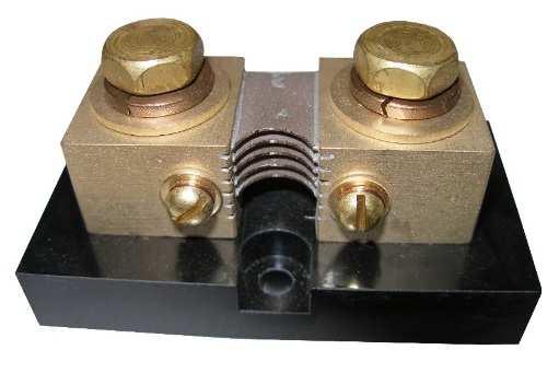 |
Figure 18 - Standard Shunt
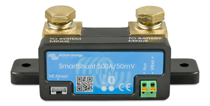
Figure 19 - SmartShunt 500A/50mV
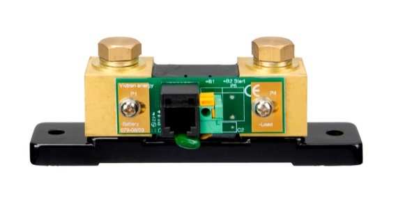 |
Figure 20 - Victron Shunt 50mV/500A
The VE Panel enclosure is set up to accept numerous controllers using an optional bracket, but Victron MPPTs are not mounted with the optional bracket. Controllers may be installed on either side of the enclosure using brackets.
 | INFO: 1 MPPT can be added to either Primary or Secondary VE Panels. |
The bracket is the standard bracket that comes with every VE Panel. If your controller must mount to the opposite side, then order a MNCCB-Left. This bracket directly accepts the MidNite Classic controller, OutBack MX60, FM60 and FM80. Some PWM controllers such as the Xantrex C40/C60 and the Morningstar Tristar 60 can also mount to this bracket by adding an additional mounting hole. The Xantrex MPPT controller does not require a bracket
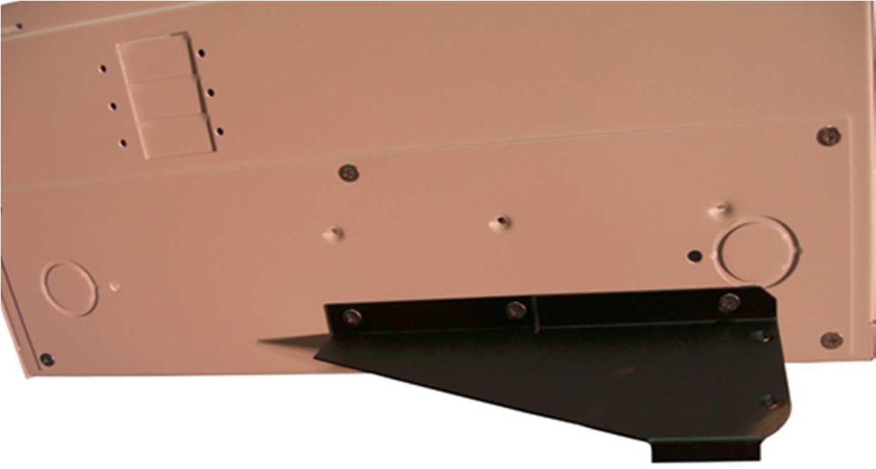
Figure 21 - Charge Controller Bracket
Wires pass through a 1” conduit knockout in the side plate. Install a 1” Close nipple, three 1” locknuts, and two bushings to complete the wire passage.
One of the locknuts is placed between the two enclosures to act as a spacer.
The VE Panel can accept up to three panel mount breakers on either side and up to seven din rail mount breakers.
Din rail breakers go up to 63 amps at the present.
Each charge controller must have a breaker/disconnect coming in from the PV combiner and also a breaker on the output of the controller. The need for breakers on both sides of the controller is an NEC requirement. For a more complete wiring diagram see Installer Supplied Connection Diagrams Figure 30.
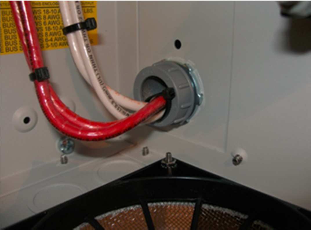
Figure 22 - PV Conduit
If PV Ground Fault Protection is required a PV Ground Fault Protection (GFP) Assembly can be installed. See Figure 23
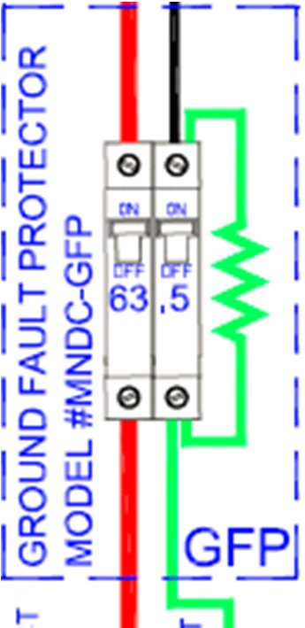
Figure 23 - Ground Fault Protection Assembly
This section provides information on the AC wiring inside the VE Panel enclosure to/from the inverter, from the incoming AC source, and to the outgoing AC distribution panel (i.e., inverter/charger sub-panel).
Before installing any AC wiring, review all safety information.
 | CAUTION: DO NOT connect the Victron inverter’s output to an AC power source. This could cause severe damage to the inverter and is not covered under warranty. |
The Inverter AC Bypass Switch Breaker allows the inverter loads to continue to be powered by the incoming AC source (utility or generator) while isolating the inverter or battery system if maintenance or repair is needed.
This AC Bypass assembly is pre-wired in the VE Panel between the incoming AC source and the inverter load panel (i.e., sub-panel).
It connects the incoming AC source to the inverter’s AC loads; either through the “inverter” or directly by “bypassing” the inverter.
This bypass switch assembly uses a mechanical slide assembly to prevent both breakers from being ON at the same time, but both can be OFF at the same time.
This bypass switch is normally set to ‘OFF” (inverter not bypassed), but can be easily moved to “ON” (bypassing the inverter) allowing the AC loads to continue to be powered while the inverter and/or battery bank is being serviced.
 | CAUTION: All AC loads should be turned off before switching the bypass switch breaker. |
 | INFO: When the bypass switch is ON the connected equipment is directly powered from the AC source (utility or generator), and will go off if the AC source is disconnected or turned off. |
Use Figures in Section 4.3 to view the AC connection points inside the VE Panel enclosure.
The VE Panel comes wired with 6AWG wire for all AC circuits for the 3k and 5k versions.
The output of the inverter terminals are wired to the VE Panel AC output terminal busbars.
Correctly sized conductors are prewired from the VE Panel breakers to connect to the inverter AC line and neutral input and output. AC1 in line and neutral, AC2 in line and neutral, and AC1 out line and neutral conductors are marked as such. These wires also connect to the VE Panel terminal busbars of the same name.
Installer connections are shown in Figure 30.
Refer to the list of torque values in section 3.1.
The 3k and 5k VE Panels are supplied with 2 pole 60 Amp continuous duty rated breakers for the generator input, utility input and AC input/output bypass switch.
Most generators come with a UL489 branch circuit output breaker. All main distribution/service entrance panels such as Square D utilize UL489 branch circuit rated breakers.
The AC breakers supplied in the VE Panel are supplementary protection listed to UL1077. These breakers are used as disconnects or switches, but not as branch circuit devices. Branch circuit breakers made for a residential service entrance panels are typically thermal breakers. These breakers are not allowed under NEC guidelines to normally carry more than 80% of their rating. That means a 60 amp Square D QO stab in breaker may only be sized for 48 amps continuous power.
The breakers in the VE Panel are a hydraulic/magnetic variety and are allowed under NEC guidelines to carry full rated current. The VE Panel comes with 60 amp hydraulic/magnetic breakers.
Busbars are provided for easy connections from a generator and or the utility and also for an AC sub-panel.
The AC input and output busbars are also the ideal place to connect lightning or surge arrestors.
The output busbar must not be connected to the main distribution panel in a utility connected installation. The main utility connected distribution panel will go dead during an outage. Only circuits connected to the AC output busbar (sub-panel) will have power during a power outage. Do not try to back feed a utility connected distribution panel from the output of the inverter/charger.

Figure 24 - Grid Tied Battery Backup Flow Diagram
The flow diagram in Figure 24 shows AC current flow direction for a battery backed up grid tie system.
DC current flow is not shown. Note that all loads powered by the inverter must be connected to the AC sub-panel on the right.
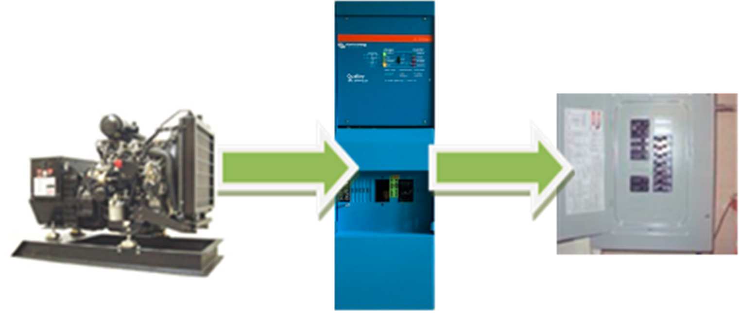
Figure 25 * shows AC current flow in an off-grid system.
Figure 25 shows AC current flow in an off-grid system.
DC current flow is not shown.
In a utility connected system, only the loads connected to the AC output Subpanel will have power during an outage. The main service entrance loads will have no power.
 | INFO: The inverter/charger AC OUT 2 is not supported with the VE Panel. |
The VE Panel comes with a green 4 AWG ground wire.
The ground chassis lug on the bottom right of the inverter/charger is the same electrical connection as the two inside the wiring compartment of the 5kVA Quattro. For the 3kVA Quattro and MultiPlus only one ground terminal stud that is located in the bottom right of the inverter/charger chassis. See Figures 26 and 27.
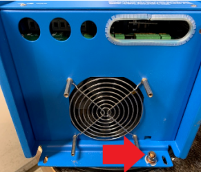 |
Figure 26 - 3kVA Ground Connection Point
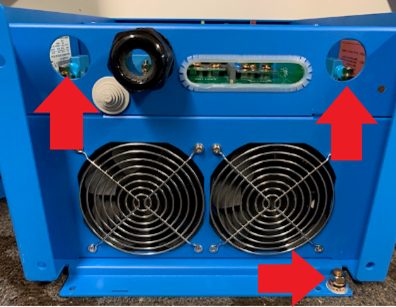 |
Figure 27 - 5kVA Ground Connection Points
You may use this large terminal stud as the one single ground connection to the inverter/charger and then connect all other grounds to the VE Panel ground bus. The 5kVA has three ground terminal studs are bonded and only one is necessary or as dictated by Authority Having Jurisdiction (AHJ).
Since the VE Panel ground, inverter/charger chassis ground and wiring compartment grounds are all at the same potential, you may use any and all as required although electrical inspectors are used to finding all grounds landing on just one busbar.
The VE Panel ground bus is the proper place for this single point ground on an off-grid system. Your main distribution panel ground is the proper AC ground for utility connected systems.
Use the VE Panel ground bus for the DC grounds in a utility connected system. Inspectors will want to see a separate ground wire from AC and DC on a utility connected system.
You can use a single ground wire from the VE Panel for AC and DC for an off-grid installation. Refer to Figure 30 for installer connection points.
All AC electrical systems in North America must have an AC Neutral to Earth Ground bonding connection, and only one neutral to ground connection per system
A typical distribution panel such as Square D makes this bond by use of a bonding green screw.
That green screw grounds the neutral bus bar when installed.
Electrical inspectors are used to looking in the main distribution panel for this electrical bond.
In a grid tie battery back-up installation, this bond has already been made in the main distribution/service entrance panel.
Do not make this connection inside the VE Panel when connected to utility service.
In an off-grid installation where there is no utility connection, the bond should be done inside the VE Panel as shown in Figure 28.
6AWG Neutral to Ground bonding wire.
The bond should be done at the power source and since the VE Panel is central to the power generation, it is considered the source.
Some electrical inspectors are used to looking for this bond to be accomplished in the distribution panel. They may ask you to move it to where they feel comfortable finding it. Don’t fight it. The bond can made in the main distribution panel or VE Panel.
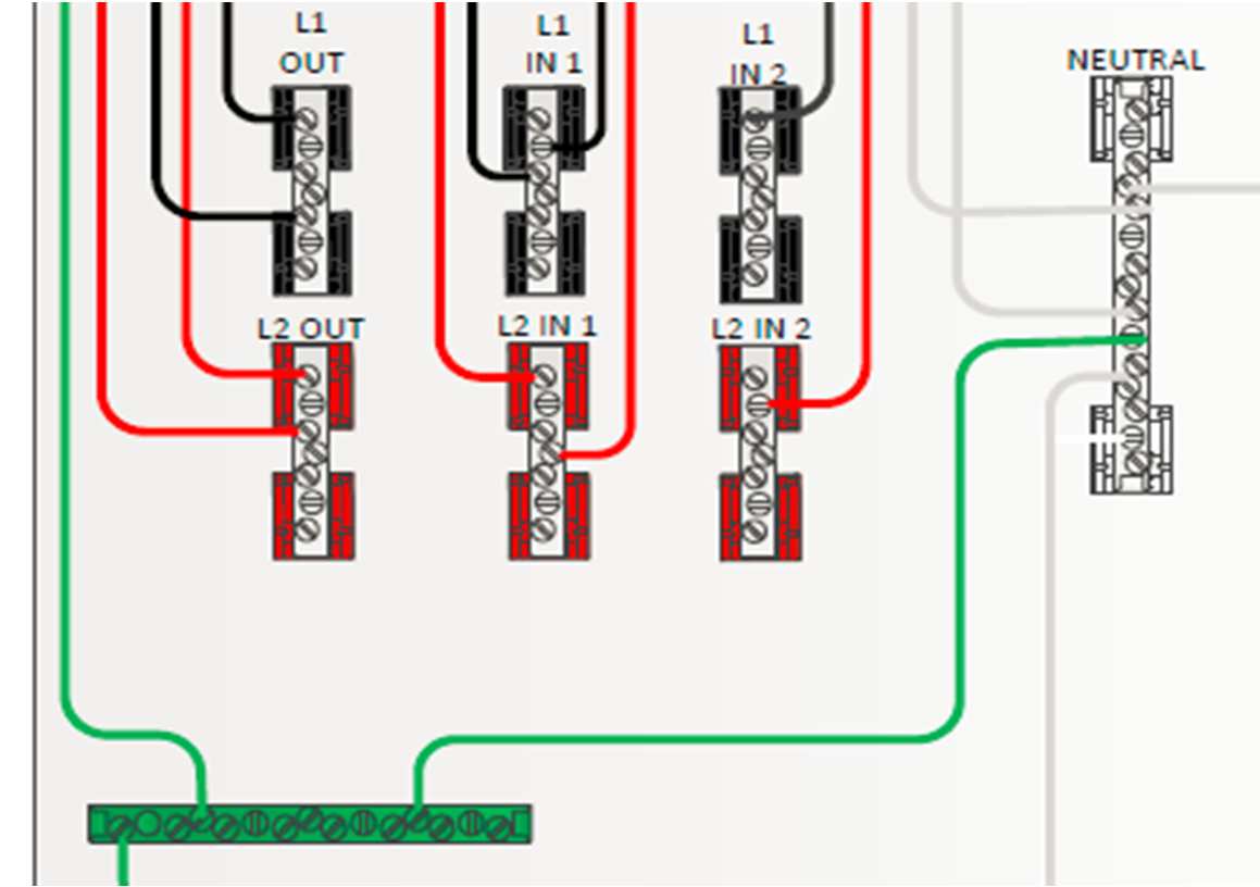
Figure 28 - Neutral to Ground Bond Off-Grid Only
 | INFO: The neutral to ground relay for the MultiPlus or Quattro must be disabled in VEConfigure3 or VictronConnect. |
The Battery + lightning arrestor has marginal value since the batteries make a pretty large arrestor themselves. See Figure 29.
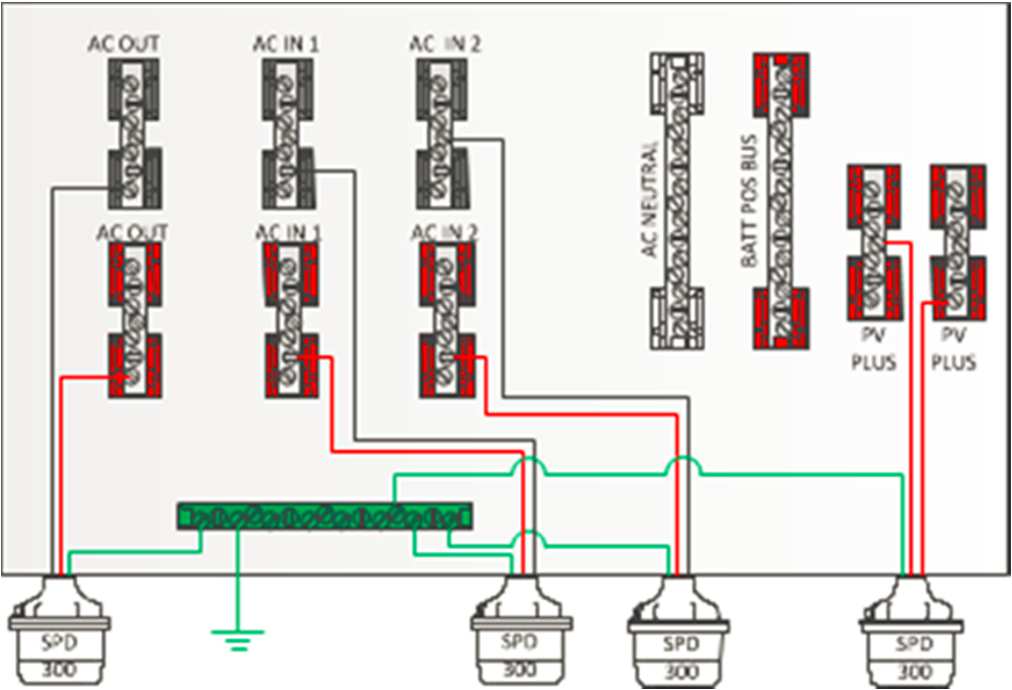
Figure 29 - Lightning Arrestors
Below is a diagram of all wiring to be done by the installer.
 | WARNING: All parts within VE Panel are live when energized. |
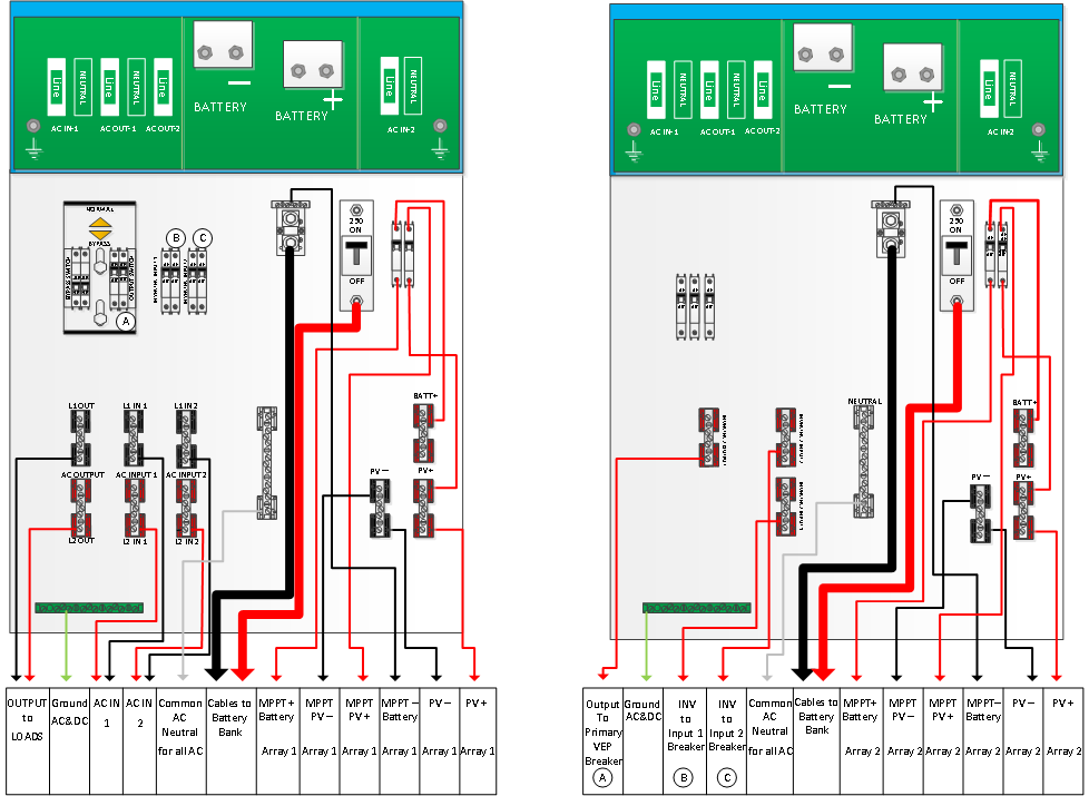
Figure 30 - 5kVA Installer Supplied Connections (3kVA Similar)
Refer to Figures in section 4.3 for connections to MultiPlus or Quattro.