The Victron Energy Autotransformer (AT) supports many different wiring configurations. It can increase your system’s ability to adapt to different design and Voltage requirements, and also be used to balance loads in split-phase 120/240Vac systems. Specialty systems such as boats and vehicles may face different shore configurations while traveling, an autotransformer can help by being flexible and enabling connections to most grid configurations.
The Victron Energy Autotransformer has the ability to use a ground/earth relay to create a Neutral to Ground bond in the AT itself, if coupled with a Victron Energy MultiPlus or Quattro and the relay terminals are interconnected.
This manual will explain the many uses for this device and how to safely install and wire it. Below there are general examples of four ways the Autotransformer can be applied. There are several specific uses that can be realized in the integration of an autotransformer into an installation and are explained in section 2.4. The AT does not provide isolation. See section 4 for specifications.
120/240V - 32A
120/240V - 100A
Pass through current is 32A and 100A respectively, the transformers are 100% equal in both models. See more information in section 2.7.
Balancing a Generator or Stacked Inverters
Full power from a split phase supply source such as a generator or stacked inverters is sometimes limited, as a single phase load cannot draw more energy than its individual leg will allow even though the other leg isn’t fully utilized.
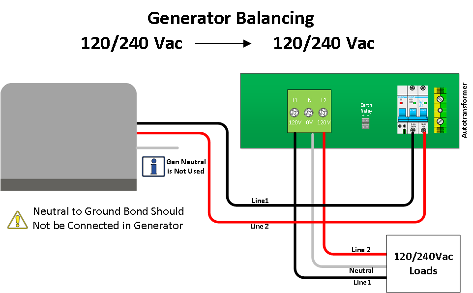
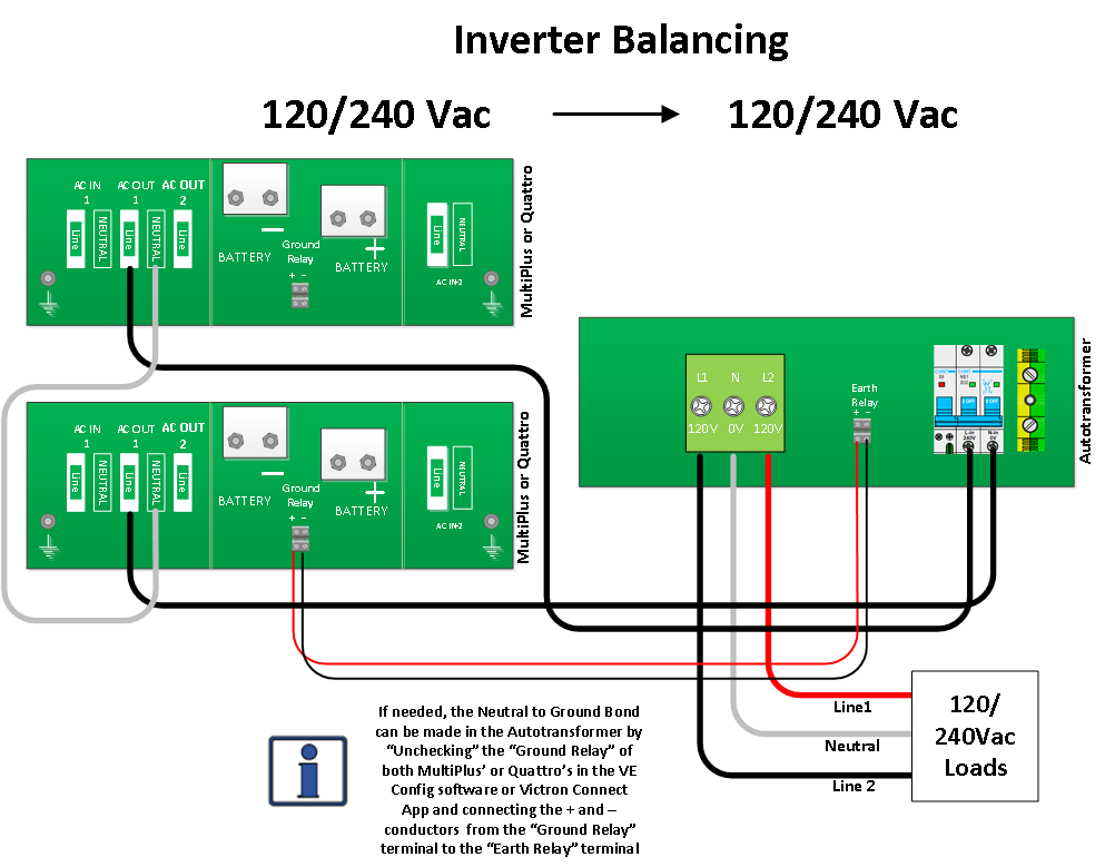
If balancing a generator or stacked inverters is required, the AT can accomplish this by leaving the neutral of the split phase supply unused, to create a new neutral, as shown in the illustration below. Any load unbalance is “absorbed” by the autotransformer.
The two legs of a split phase from an AT are independent from each other, beside the fact there is a fixed phase shift between them. This (180Deg) phase shift means the sine-wave of both legs is in full opposite (creating a double voltage from leg to leg rather than that of leg to Neutral).
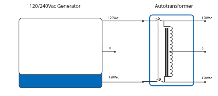
With an AT, energy from one leg can be “transferred“ to the other leg which creates a far higher total load level, unlocking the full potential of power available from a generator or stacked inverters..
See diagram below for wiring instructions.
Alternative to Stacked Inverters.
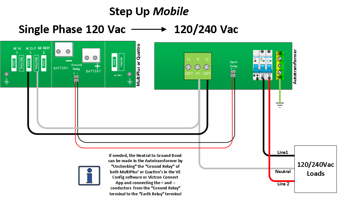
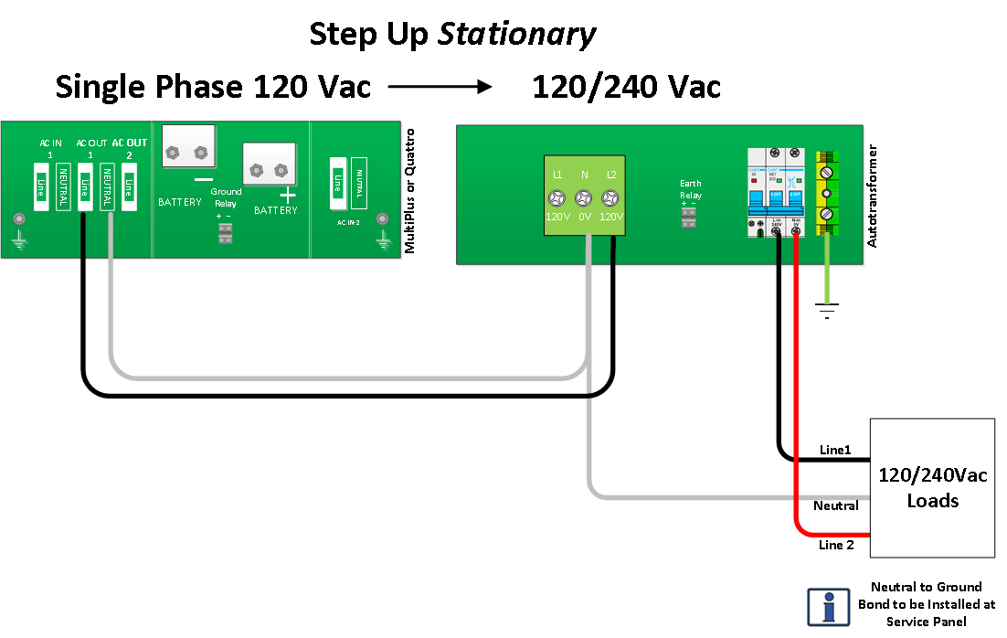
Loads such as deep well water pumps and air conditioning units sometimes require Split-Phase 120/240Vac power.
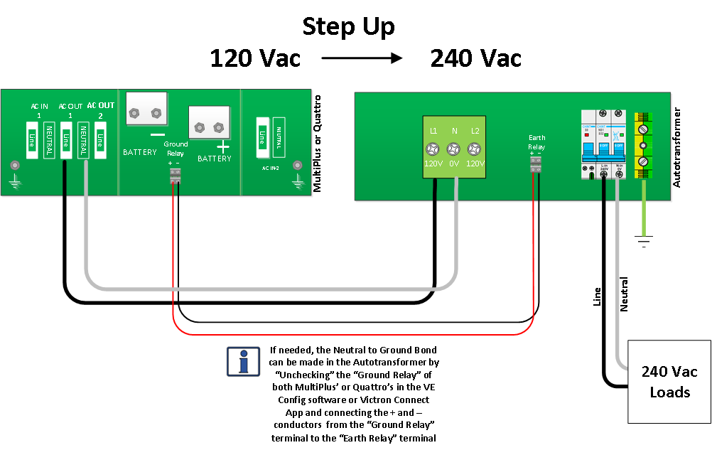
When the available AC power source is not what is needed in the installation, the autotransformer can create the needed voltage by doubling the incoming voltage.
The alternative to stacking two 120Vac inverters to provide a 120/240Vac Split-Phase is a single 120Vac inverter with an additional autotransformer.
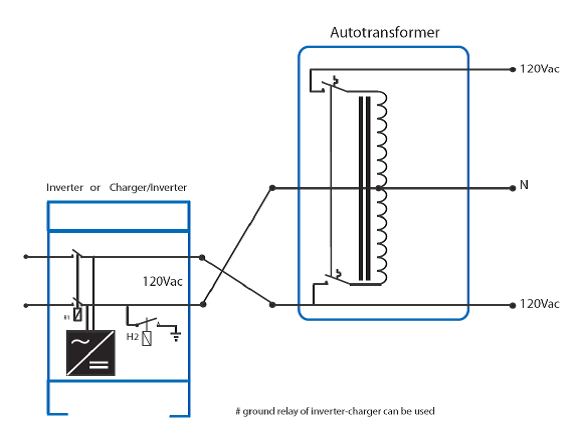 |
Other possible cases for stepping up the Voltage are shown in the wiring diagrams below.
 |
 |
 |
Flexibility in Using Split-Phase for Single-Phase Inverters
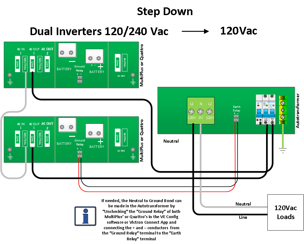
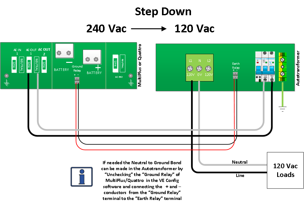
One case for using the autotransformer to step down voltage could be in installations that use a Split-Phase generator and a Single-Phase inverter, the autotransformer makes it possible to use all available power from both legs of the generator to power loads and to charge batteries.
When the available AC power source is not what is needed in the installation the autotransformer can create the needed voltage by decreasing the incoming voltage.
Other possible cases for stepping down the Voltage are shown in the wiring diagrams below.
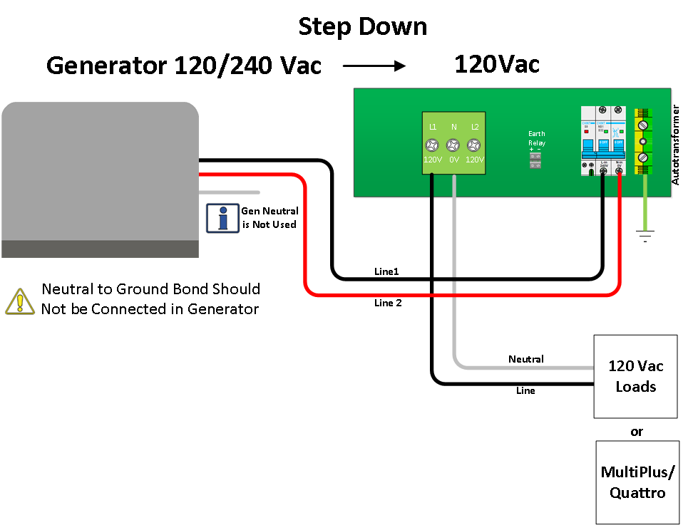 |
 |
 |
In TT configurations, common in residential and mobile energy systems, the neutral (N) of the AC system is grounded. This setup enhances safety, enabling Ground Fault Circuit Interrupters (GFCIs) to trip during earth faults. The connection between neutral and protective earth (N-PE) facilitates current flow in secondary circuitry, which GFCIs detect, interrupting the circuit to prevent hazards.
In some systems, an autotransformer can also “create” a neutral different from the incoming neutral. It incorporates a ground relay for this purpose and can be controlled by an inverter/charger.
This involves the following:
For a MultiPlus or Quattro: Deactivate the inverter/charger's internal ground relay via the SW1 slide switch next to the "ground relay" terminal block. In the inverter/charger settings, ensure that the ground relay is enabled; do not disable it. Then, connect the inverter/charger “ground relay” terminal block to the autotransformer "earth" terminal block using positive and negative conductors.
For a MultiPlus-II: Deactivate the inverter/charger's internal ground relay by disabling the ground relay in the inverter/charger settings. Then, connect the inverter/charger “ground relay” terminal block to the autotransformer "earth" terminal block using positive and negative conductors.
Refer to sections 2.3.1 through 2.3.3 for examples using the ground relay.
| Note that the inverter/charger uses 24V to control the autotransformer relay. It is important to note that this voltage is consistently 24V across all inverter/charger models, regardless of whether their rated voltage is 12, 24, or 48V. |

In case of overheating, the autotransformer is disconnected from the supply. When the transformer is warm the fan will operate and the Red LED be illuminated. Disconnect some of the 120V load if this occurs.
When the transformer is overheated the MCB will switch off. The little blue switch will be out of the MCB.
To reset this manually cycle the circuit breaker.
In case of over current the MCB will switch off. Disconnect some of the load.
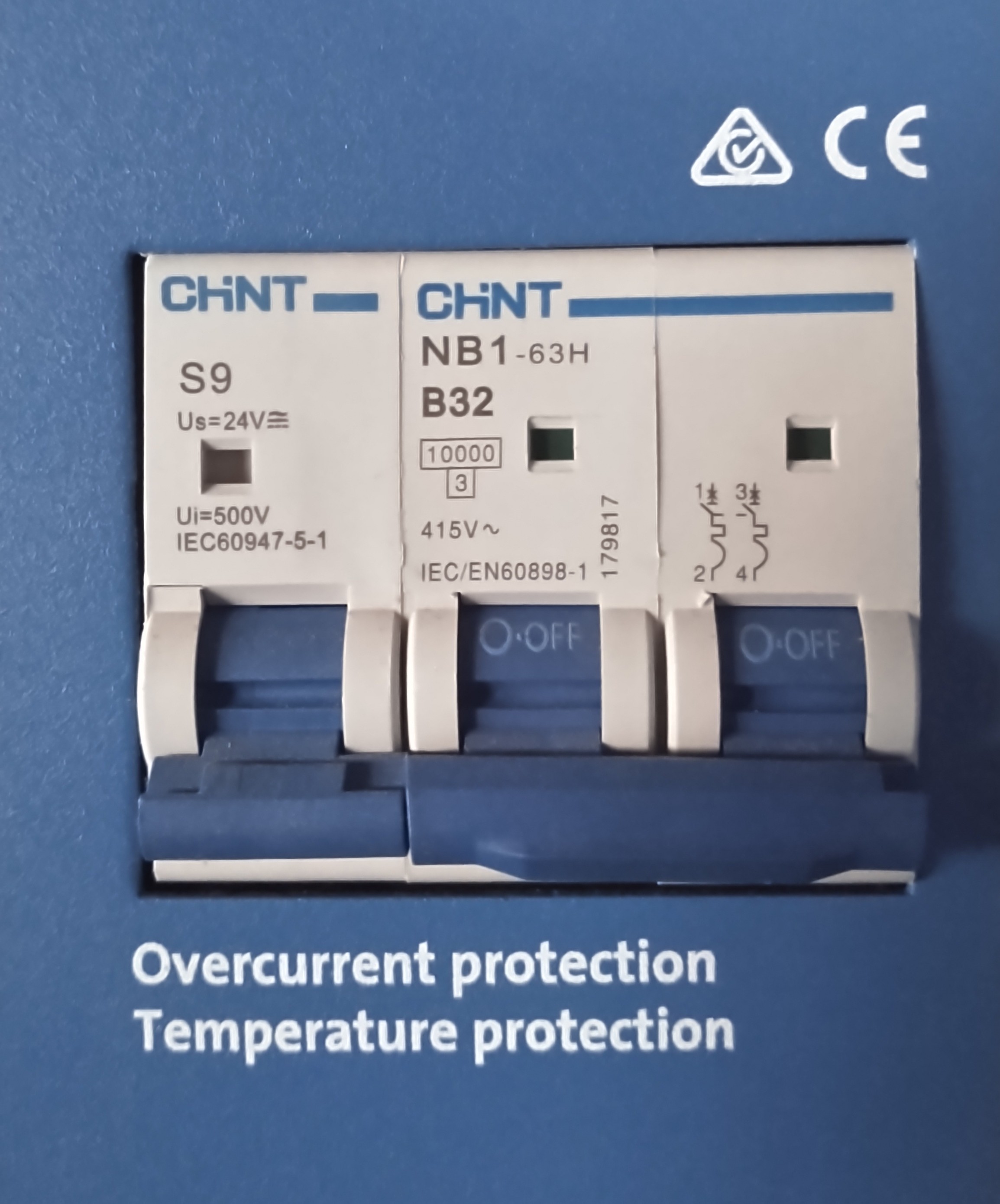 |
| The MCB is for Over Current and Temperature Protection and switching the unit ON/OFF. |
The Autotransformer comes in two models, a 32A model and a 100A model. This value is defined in the amount of current there can be in pass through, so in other words the current which is forwarded without being converted. The transformer itself is equal in both models and has a 32A capacity (peak) and 28A nominal. This is the maximal current that can be used to transfer energy from leg to leg or from 120Vac to 240Vac.