With the procedures below, most errors can be quickly identified. If an error cannot be resolved, please refer to your Victron Energy supplier.
Problem | Cause | Solution |
No output voltage on AC-out-2, even after waiting. | in inverter mode | AC input is not connecting. Follow steps in MultiPlus generator FAQ. |
Unit will not switch over to generator or mains operation. | Circuit breaker or fuse in the AC-in input is open as a result of overload. | Remove overload or short circuit on AC-out-1 or AC-out-2, and reset fuse/breaker. |
Inverter operation not initiated when switched on. | The battery voltage is excessively high or too low. No voltage on DC connection. | Ensure that the battery voltage is within the correct range. |
'Low battery' | The battery voltage is low. | Charge the battery or check the battery connections. |
'Low battery' (Shutdown) | The converter switches off because the battery voltage is too low. | Charge the battery or check the battery connections. |
Overload | The converter load is higher than the nominal load. | Reduce the load. |
'Overload' (Shutdown) | The converter is switched off due to excessively high load. | Reduce the load. |
'Over Temperature' | The environmental temperature is high, or the load is too high. | Install the converter in cool and well-ventilated environment, or reduce the load. |
'Low Bat V Overload' (Shutdown) | Low battery voltage and excessively high load. | Charge the batteries, disconnect or reduce the load, or install higher capacity batteries. Fit shorter and/or thicker battery cables. |
'High DC Ripple' | Ripple voltage on the DC connection exceeds 1,5Vrms. | Check the battery cables and battery connections. Check whether battery capacity is sufficiently high, and increase this if necessary. |
'DC Ripple Shutdown' | The inverter is switched off due to an excessively high ripple voltage on the input. | Install batteries with a larger capacity. Fit shorter and/or thicker battery cables, and reset the inverter (switch off, and then on again). |
The charger does not operate. | The AC input voltage or frequency is not within the range set. | Ensure that the AC input is between 185VAC and 265VAC, and that the frequency is within the range set (default setting 45-65 Hz). |
Circuit breaker or fuse in the AC-in input is open as a result of overload. | Remove overload or short circuit on AC-out-1 or AC-out-2, and reset fuse/breaker. | |
The battery fuse has blown. | Replace the battery fuse. | |
The distortion or the AC input voltage is too large (generally generator supply). | Turn the settings WeakAC and dynamic current limiter on. | |
The charger does not operate. 'Bulk Protection' shown. | is in 'Bulk protection' mode thus, the maximum bulk charging time of 10 hours is exceeded. Such a long charging time could indicate a system error (e.g. a battery cell short-circuit). | Check your batteries. NOTE: You can reset the error mode by switching off and back on the . The standard factory setting of the 'Bulk protection' mode is switched on. The 'Bulk protection' mode can be switched off with help of VEConfigure only. |
The battery is not completely charged. | Charging current excessively high, causing premature absorption phase. | Set the charging current to a level between 0.1 and 0.2 times the battery capacity. |
Poor battery connection. | Check the battery connections. | |
The absorption voltage has been set to an incorrect level (too low). | Set the absorption voltage to the correct level. | |
The float voltage has been set to an incorrect level (too low). | Set the float voltage to the correct level. | |
The available charging time is too short to fully charge the battery. | Select a longer charging time or higher charging current. | |
The absorption time is too short. For adaptive charging this can be caused by an extremely high charging current with respect to battery capacity, so that bulk time is insufficient. | Reduce the charging current or select the 'fixed' charging characteristics. | |
The battery is overcharged. | The absorption voltage is set to an incorrect level (too high). | Set the absorption voltage to the correct level. |
The float voltage is set to an incorrect level (too high). | Set the float voltage to the correct level. | |
Poor battery condition. | Replace the battery. | |
The battery temperature is too high (due to poor ventilation, excessively high environmental temperature, or excessively high charging current). | Improve ventilation, install batteries in a cooler environment, reduce the charging current, and connect the temperature sensor. | |
The charging current drops to 0 as soon as the absorption phase initiates. | Defective battery temperature sensor | Disconnect the temperature sensor plug in the . If charging functions correctly after approximately 1 minute, the temperature sensor should be replaced. |
The battery is over-heated (+50°C) | Install the battery in a cooler environment | |
Reduce the charging current | ||
Check whether one of the battery cells has an internal short circuit | ||
A VE.Bus system can display various error codes. These codes are displayed on the front GX display screen.
To interpret a VE.Bus error code correctly, you should refer to the VE.Bus error codes documentation
https://www.victronenergy.com/live/ve.bus:ve.bus_error_codes.
Code | Meaning: | Cause/solution: |
|---|---|---|
1 | Device is switched off because one of the other phases in the system has switched off. | Check the failing phase. |
3 | Not all, or more than, the expected devices were found in the system. | The system is not properly configured. Reconfigure the system. If the error persists, possible communication cable error. Check the cables and switch all equipment off, and then on again. |
4 | No other device whatsoever detected. | Check the failing unit. Check the communication cables. |
5 | Overvoltage on AC-out. | Check the AC cables. |
10 | System time synchronisation problem occurred. | Should not occur in correctly installed equipment. Check the communication cables. |
14 | Device cannot transmit data. | Check the communication cables (there may be a short circuit). |
17 | One of the devices has assumed 'master' status because the original master failed. | Check the failing unit. Check the communication cables. |
18 | Overvoltage has occurred. | Check AC cables. |
22 | This device cannot function as 'slave'. | This device is an obsolete and unsuitable model. It should be replaced. |
24 | Switch-over system protection initiated. | Should not occur in correctly installed equipment. Switch all equipment off, and then on again. If the problem recurs, check the installation. Possible solution: increase lower limit of AC input voltage to 210 VAC (factory setting is 180 VAC) |
25 | Firmware incompatibility. The firmware of one the connected devices is not sufficiently up to date to operate in conjunction with this device. | 1) Switch all equipment off. 2) Switch the device returning this error message on. 3) Switch on all other devices one by one until the error message reoccurs. 4) Update the firmware in the last device that was switched on. |
26 | Internal error. | Should not occur. Switch all equipment off, and then on again. Contact Victron Energy if the problem persists. |
A GX card factory reset is performed by inserting a USB stick containing a specific reset file into the USB port. The reset requires Venus firmware version 2.12 or higher and does not involve buttons or screens.
If the GX card is locked out due to a forgotten Remote Console password.
If residual memory from a prior environment (e.g., discovered AC PV inverters) needs to be removed.
To reset misconfigured settings causing unusual behaviour.
If the data partition is full due to modifications to the GX card operating system
If there is a bug in a beta-testing firmware version.
If there are no issues, but a clean start is wanted.
Download the venus-data-90-reset-all.tgz file.
Copy the file onto a blank, freshly formatted FAT32 USB stick. Do not unpack, unzip, or rename the file.
If the GX card is running firmware between versions 2.12 and 3.10, only a single file execution is supported. In this case, either update the firmware on the GX card or rename the downloaded file to "venus-data.tgz" before copying it to the USB stick.
Turn the unit off.
Insert the USB stick and turn the unit back on.
Wait until the GX card has fully started up.
Remove the USB stick.
Power cycle the unit or use the Reboot function in the Settings → General menu.
A Venus OS re-installation is required if the reset to factory default does not work. For this refer to the GX device - Venus OS re-installation chapter.
Caution
Only use this procedure as a last resort after the GX device - Factory reset procedure and all other troubleshooting options have been exhausted!
This procedure is intended to fix a bricked device and is unsuitable for devices that boot up but exhibit strange behaviour.
Warning
This procedure involves opening the unit's cover and connecting the battery while the unit is open. This will expose you to dangerous voltages.
This procedure should only be performed by Victron Energy dealers, distributors, electric technicians or professional users.
If you are unsure about performing this procedure, consult your Victron Energy dealer or distributor.
Warning
Connecting the battery while the unit is open will expose you to dangerous AC or DC voltages that cannot be isolated.
Always use insulated tools.
Prevent short circuits between the battery terminals, AC terminals and internal circuit boards.
Notice
This procedure will erase all partition data, including all settings.
After this procedure, it may be required to reset the VRM authorisation token.
Venus OS re-installation procedure EasySolar-II GX | |
|---|---|
1 | Download the installer image (venus-install-sdcard-nanopi-*.img.zip) from here: https://updates.victronenergy.com/feeds/venus/release/images/nanopi/ |
2 | Use Balena Etcher to flash the image to a microSD card. Download Etcher from here: https://etcher.balena.io/. The application automatically unzips the archive. |
3 | Turn the unit off. |
4 | Disconnect all electrical connections from the bottom of the unit. |
5 | Remove the front cover screws; there are three screws on each side and two on the bottom side. |
6 | Remove the front cover. Be cautious of the flat cable connected to the display on the cover. |
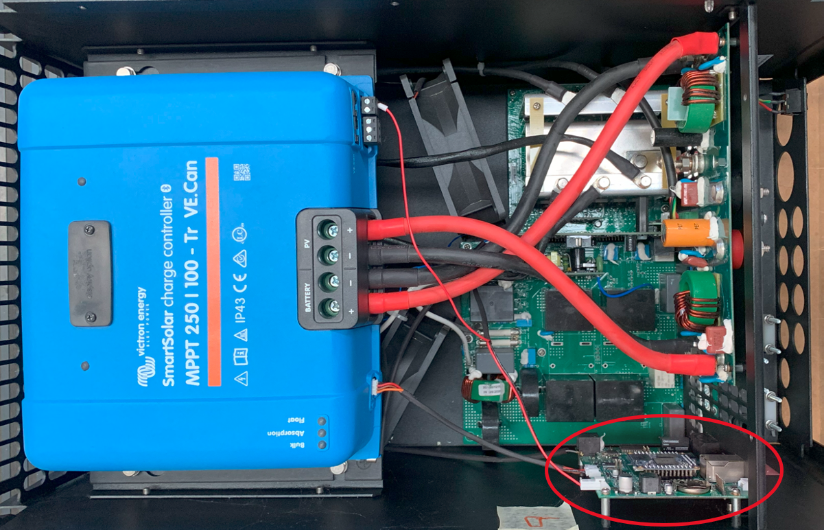
7 | Locate the GX card, indicated by the red circle in the image below.  |
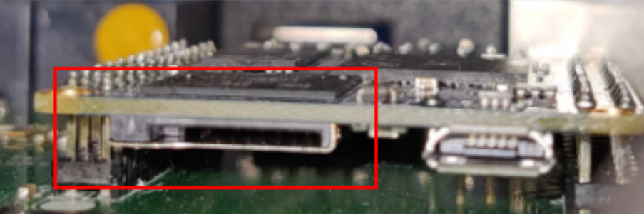
8 | Insert the microSD card into the SD card slot with the contacts pointing upwards.  |
9 | Connect the battery and turn the unit on. Wait 2 minutes for the installation process to complete. |
10 | Remove the microSD card. |
11 | Re-assemble the unit. |
12 | Power-cycle the unit. Turn the unit off, then turn it back on again. |