Mount vertically on a non-flammable surface, with the power terminals facing downwards.
Observe a minimum clearance of 10 cm under and above the product for optimal cooling.
Mount close to the battery, but never directly above the battery to prevent damage due to gassing of the battery.
Please see the Appendix of this manual for the dimension drawing; this drawing also indicates the mounting holes.
Caution
Use flexible multi-stranded copper cables for the battery connections.
The diameter of the individual strand of the cable used should not exceed 0.4mm (0.016 inch) or have a surface area exceeding 0.125mm² (AWG26).
The maximum operating temperature is 90°C (194°F).
A 16mm² cable, for example, should have at least 122 strands (class 5 or higher stranding according to VDE 0295, IEC 60228 and BS6360). Example of suitable cable: class 5 “Tri-rated” cable (it has three approvals: American (UL), Canadian (CSA) and British (BS)).
In the case of thicker strands, the contact area will be too small, and the resulting high contact resistance will cause severe overheating, eventually resulting in fire. See the below figure for examples of what cable to use and not to use.

Cable type recommendation
For correct connection of a cable to the input/output screw terminals, stranded wires with flexible and very flexible cores can be used according to:
IEC 60228 - Class 2 (stranded), Class 5 (flexible), Class 6 (very flexible)
UL486A-B - Class B/C (stranded), Class I (flexible), Class K (very flexible)
Cables with twisted cores are very stiff, which means that they are rarely used in practice. The table below provides an overview of how to recognise the different wire classes.
Single wire diameter in the bundle | ||||
|---|---|---|---|---|
Nominal cross-section | Class 5 (IEC) | Class 6 (IEC) | Class I (UL) | Class K (UL) |
9AWG | 24AWG | 30AWG | ||
6mm2 | 0.3mm | 0.2mm | ||
7AWG | 24AWG | 30AWG | ||
10mm2 | 0.4mm | 0.2mm | - | - |
6AWG | - | - | 24AWG | 30AWG |
16mm2 | 0.4mm | 0.2mm | - | - |
4AWG | - | - | 24AWG | 30AWG |
The use of ferrules is not required for cables from the above table. If an even thinner cable is used, a ferrule can help to bundle the loose wires. However, it is up to the installer to make sure that the cable is properly secured. With or without a ferrule, the connecting cable must be adequately clamped to ensure low contact resistance.
Preparation for correct mounting of fine strand wires in the screw terminal block
Cut the cable straight with no loose or staggered threads. Using a wire cutter will result in a straight cut.
Make sure no fine wires are cut when stripping the insulation.
Open the screw on the screw terminal block completely to prevent fine wires from getting caught behind the screw and bunching up. Pay particular attention to this when using the maximum wire diameter.
Tighten the screw with the correct torque; see Recommended torque and note the wire size and wire class. Never apply less than the recommended torque.
Hold the recommended torque for at least 5 seconds, this will give the screw time to settle to the set torque. This maximises the force on the wire, thereby maintaining a gas-tight contact pattern during heating and cooling cycles over time. Take the time to do it right. This is important. This is a UL486 test requirement and a requirement for all factory and field installations.
Fuse recommendation
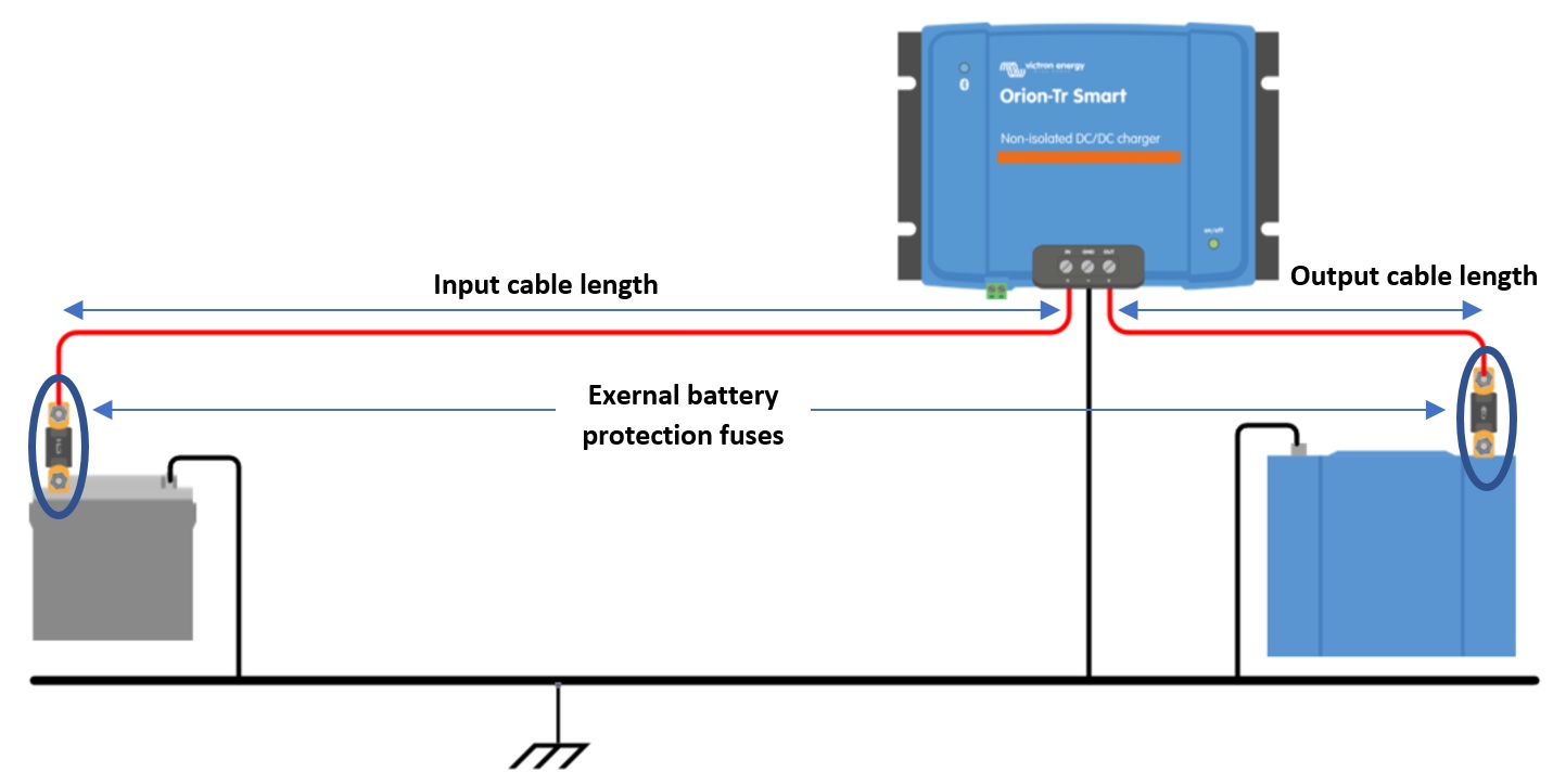 |
Figure 6: Cable and fuse recommendations |
Minimum cable gauge | ||||||
|---|---|---|---|---|---|---|
Voltage rating (Input or output) | External battery protection Fuse | 0.5m | 1m | 2m | 5m | 10m |
12V | 60A | 6mm2 | 10mm2 | 10mm2 | 16mm2 | 16mm2 |
24V | 30A | 4mm2 | 6mm2 | 6mm2 | 10mm2 | 10mm2 |
48V | 20A | 2.5mm2 | 4mm2 | 4mm2 | 6mm2 | 6mm2 |
Warning
The Orion Smart DC-DC Charger is not protected against reverse battery polarity; any damage caused by this is not covered under warranty. A device damaged by reverse polarity cannot be repaired.
Always verify the battery polarity before connecting or reconnecting the battery cables to the Orion smart charger.
Do not attempt to attach the battery cables to the Orion unless the input and output terminals are safely accessible.
Be careful not to bend individual strands when inserting the cables into the input and output terminals.
Connect the battery cables to the Orion first, verify battery polarity again and only then connect the battery.
Note
A device damaged by reverse polarity cannot be repaired. Do not attempt to open the device. The device is potted and contains no serviceable parts or fuses that can be replaced.
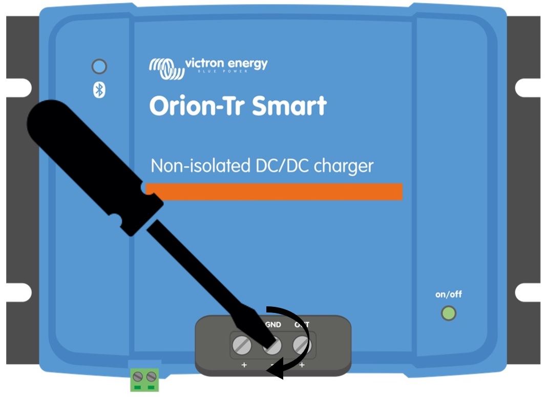 |
Torque: 1.6 Nm
Disconnect the remote on/off; remove the wire bridge or unplug the terminal block.
Connect the input supply cables.
Open the VictronConnect App to set up the product, see Power Supply Mode (always adjust the output voltage before connecting in parallel or connecting a battery).
Connect the load. The Orion is now ready for use as a power supply.
Reconnect the remote on/off to activate the product.
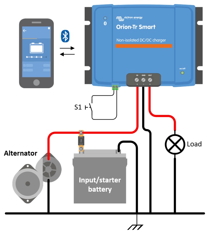
Figure 1: Typical connection setup as DC-DC power supply
Disconnect the remote on/off; remove the wire bridge or unplug the terminal block.
Connect the input supply cables.
Open the VictronConnect App to set up the product, see Charger Mode (always set up the correct charger algorithm before connecting a battery).
Connect the battery to be charged.
Reconnect the remote on/off to activate the product.
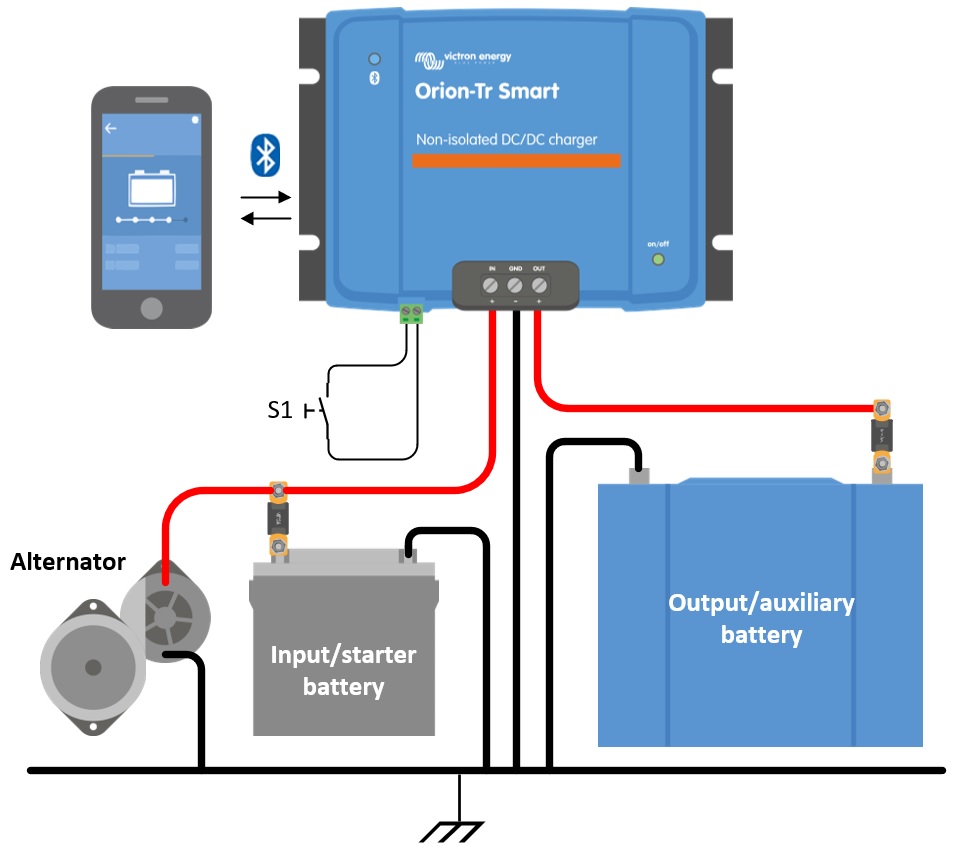
Figure 2: Typical connection setup as charger
The recommended use of the remote on/off is:
a) A switch wired between the L-H pins (On-level impedance between L-H pins: < 500kΩ)
b) A switch wired between (input/starter) battery plus and H-pin (on level: > 3V)
c) A switch between the L-pin and (input/starter) ground (on level: < 5V)
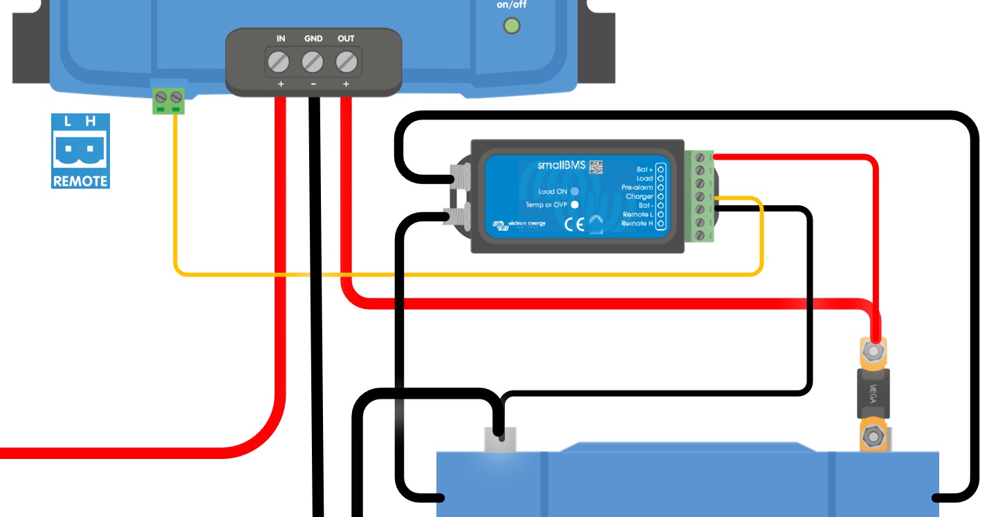
d) BMS control through the H-pin
Notice
Voltage tolerance L & H pin: +/- 70VDC
a) L-H pin wiring | b) H-pin wiring | c) L-pin wiring | |
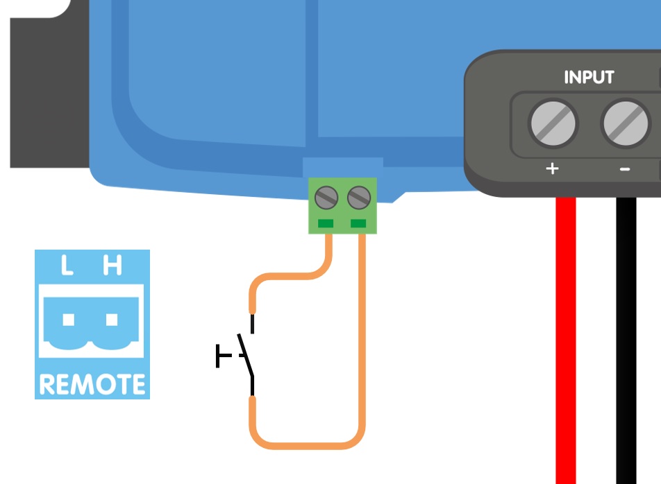 | 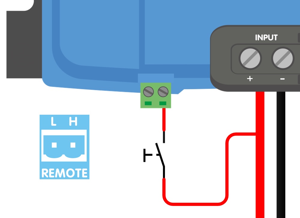 | 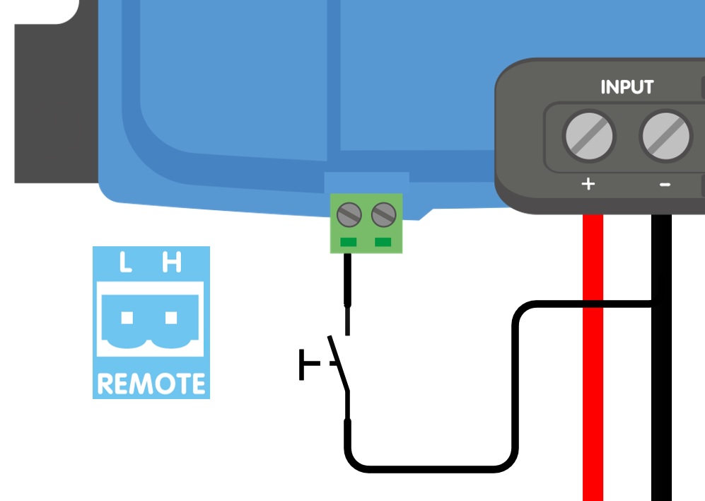 | |
d) BMS control through the H-pin | |||
| |||
Figure 3: Remote on/off connections | |||
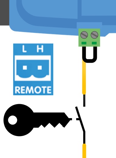
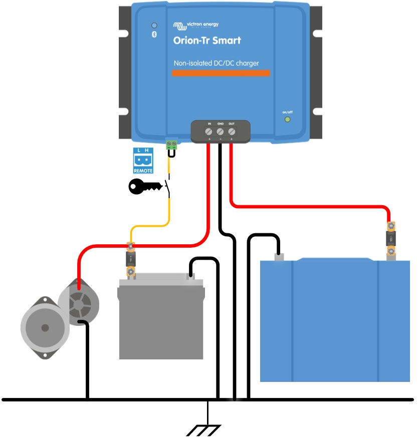
In charger mode the “engine shutdown detection sequence” determines if conditions are met to enable charging, see Engine shutdown detection. The “engine shutdown detection override” forces the charger to allow charging independently of the engine shutdown detection. Engine shutdown detection override is activated by applying >7V to the remote L-pin. This allows external control (e.g. ignition switch, CAN bus engine on detector) to enable charging.
Notice
This function does not override the remote on/off function. Remote connection a), b) or d), as shown in Figure 3 must be configured in combination with engine shutdown detection override. See examples in figure 4.
Enable charging with an ignition switch and remote on/off option a) |
  |
Enable charging with an ignition switch and remote on/off option d) |
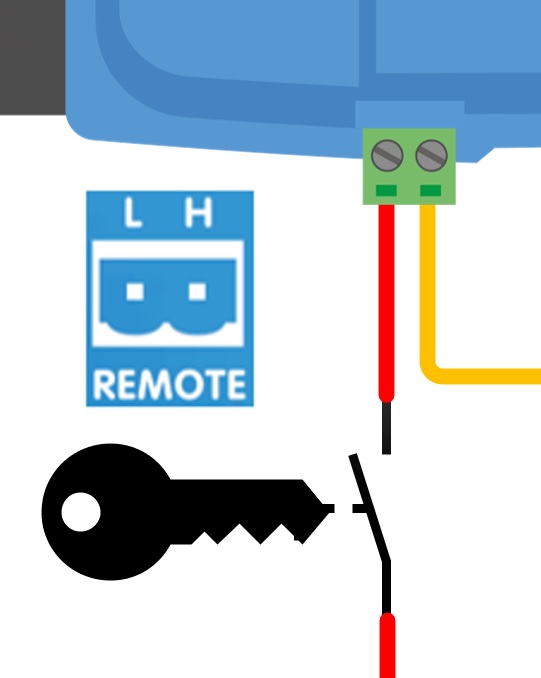 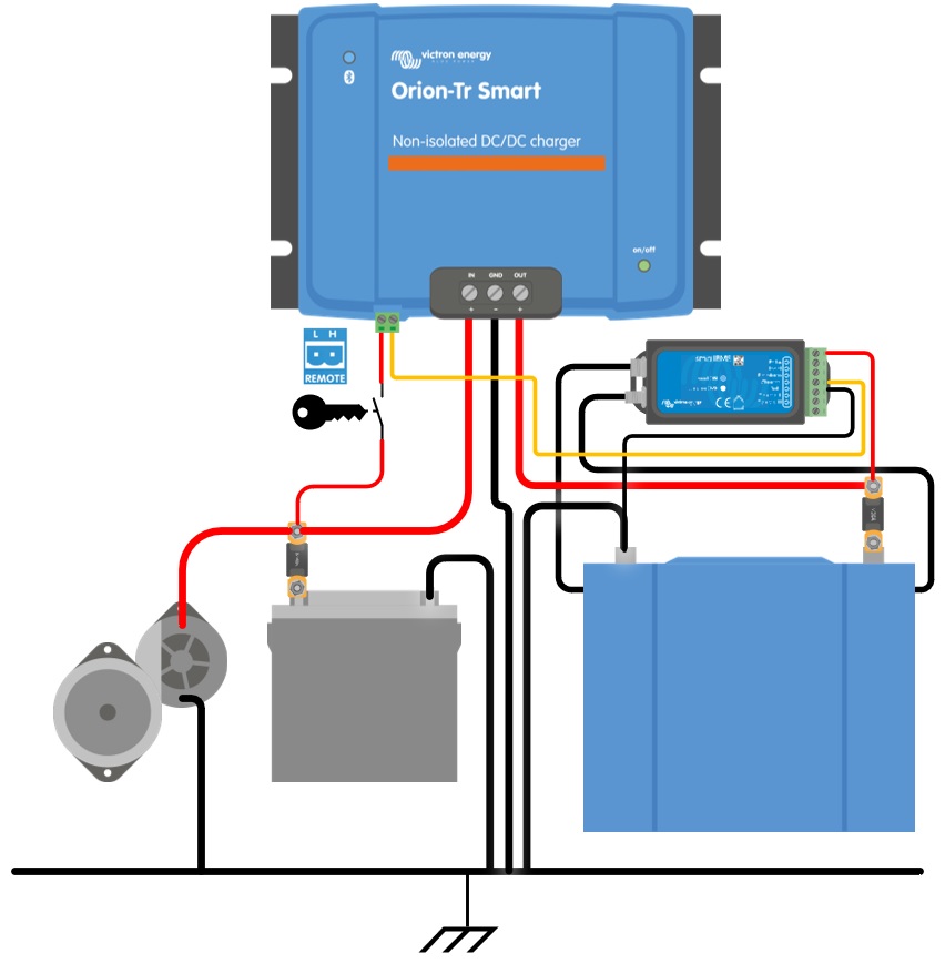 |
Figure 4: Engine shutdown detection override connection diagram
Note
If the ignition switch in figure 4 is switched off, the charger will return to “engine shutdown detection” mode, it will not turn off the charger.
To force enable/disable charging (i.e turn the ORION on/off) without the “engine shutdown detection”, a remote option as given in Remote on/off wiring must be wired, and the engine shutdown detection must be switched off in VictronConnect, see figure 5.
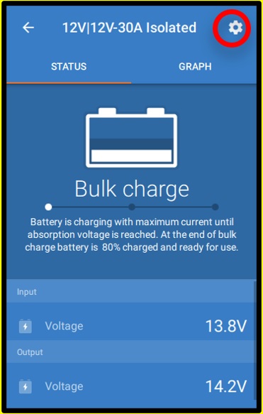 | 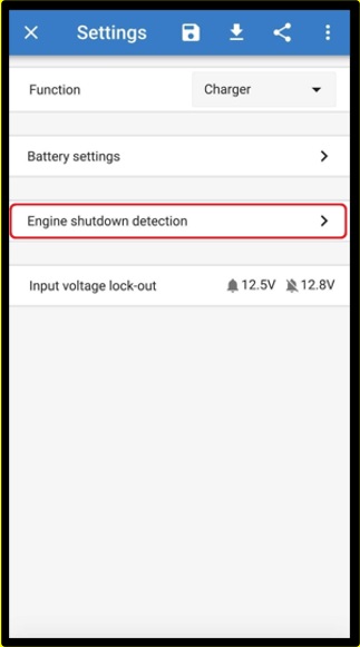 | 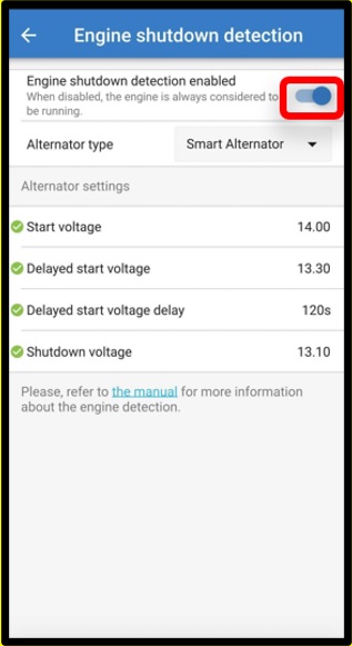 |
Figure 5: Disable engine shutdown detection
Warning
When the engine shutdown detection has been switched off in Victron Connect (‘forced charging’), current will be drawn from the starter battery even if the engine is not running.
Note
During ‘forced charging’ the input voltage lockout is the only limit left to disable charging automatically; make sure this level is not set too low, in most applications 12.5V is sufficiently low.
