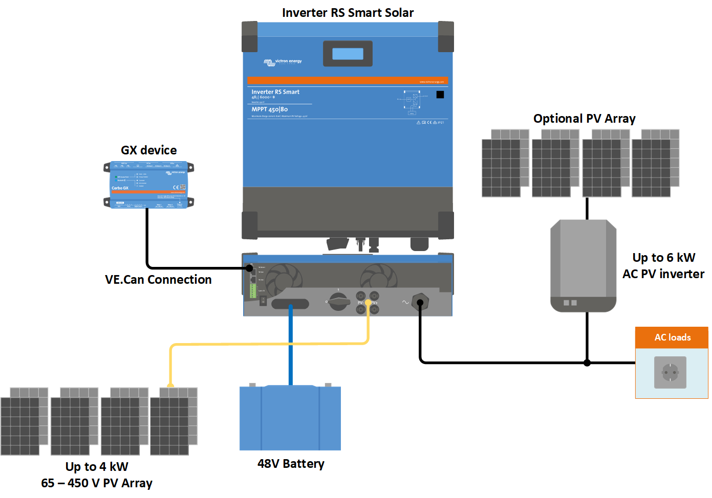
In this section:
User I/O Connector is located on bottom left side of connection area, diagram shows 3 perspectives. Left Side - Top - Right Side
Number | Connection | Description |
|---|---|---|
1 | Relay_NO | Programmable relay Normally Open connection |
2 | AUX_IN - | Common negative for programmable auxiliary inputs |
3 | AUX_IN1+ | Programmable auxiliary input 1 positive connection |
4 | AUX_IN2+ | Programmable auxiliary input 2 positive connection |
5 | REMOTE_L | Remote on/off connector Low |
6 | REMOTE_H | Remote on/off connector High |
7 | RELAY_NC | Programmable relay Normally Closed connection |
8 | RELAY_COM | Programmable relay common negative |
9 | TSENSE - | Temperature Sensor negative |
10 | TSENSE + | Temperature Sensor positive |
11 | VSENSE - | Voltage Sensor negative |
12 | VSENSE + | Voltage Sensor positive |
 |
3 Phase diagram

Parallel diagram

