The configuration option of either Grid Meter, PV Inverter, Generator or AC Meter is set in the GX device. For details on GX device configuration see the GX device configuration chapter. This selection will affect how the system should be wired and how the information received from the meter is displayed on the screen.
See the below diagrams for the different wiring options. Note that wherever the word "Fuse" appears in the diagrams, a 315 mA fuse should be used, if required by local law.
 |
EM24 3-phase wiring
Note
When used to measure a PV Inverter, terminals 1, 4 and 7 should face the PV inverter to ensure correct direction of current and power.
Single-phase, single function
 |
EM24 connected as a single-phase, single function grid meter
Note the jumper between terminals 1 and 4. You do not need this connection if you have the version AV2 of the sensor.
The diagrams show the wiring when used as a grid meter.
To measure a single-phase PV inverter in a 3-phase system, connect all 3 phases to the grid phasing terminals (3, 6 and 9). Now you can chose on which phase you want the PV inverter by connecting the L1 line of the PV inverter to terminal 1, 4 or 7.
Single-phase, dual function
The EM24 Ethernet does not support dual function. If you wish to use a three-phase meter in a single phase installation to measure the grid on one input and PV inverter output on another phase, we suggest using the EM540 or two single-phase meters.
Front selector
Change the front selector so it is not in the locked state. This allows it to be automatically configured by the GX Device. The front selector is located next to the display as indicated in the image above.
After proper connection and powering up, the meter(s) will be visible on the GX device in the Settings → Energy meters menu:
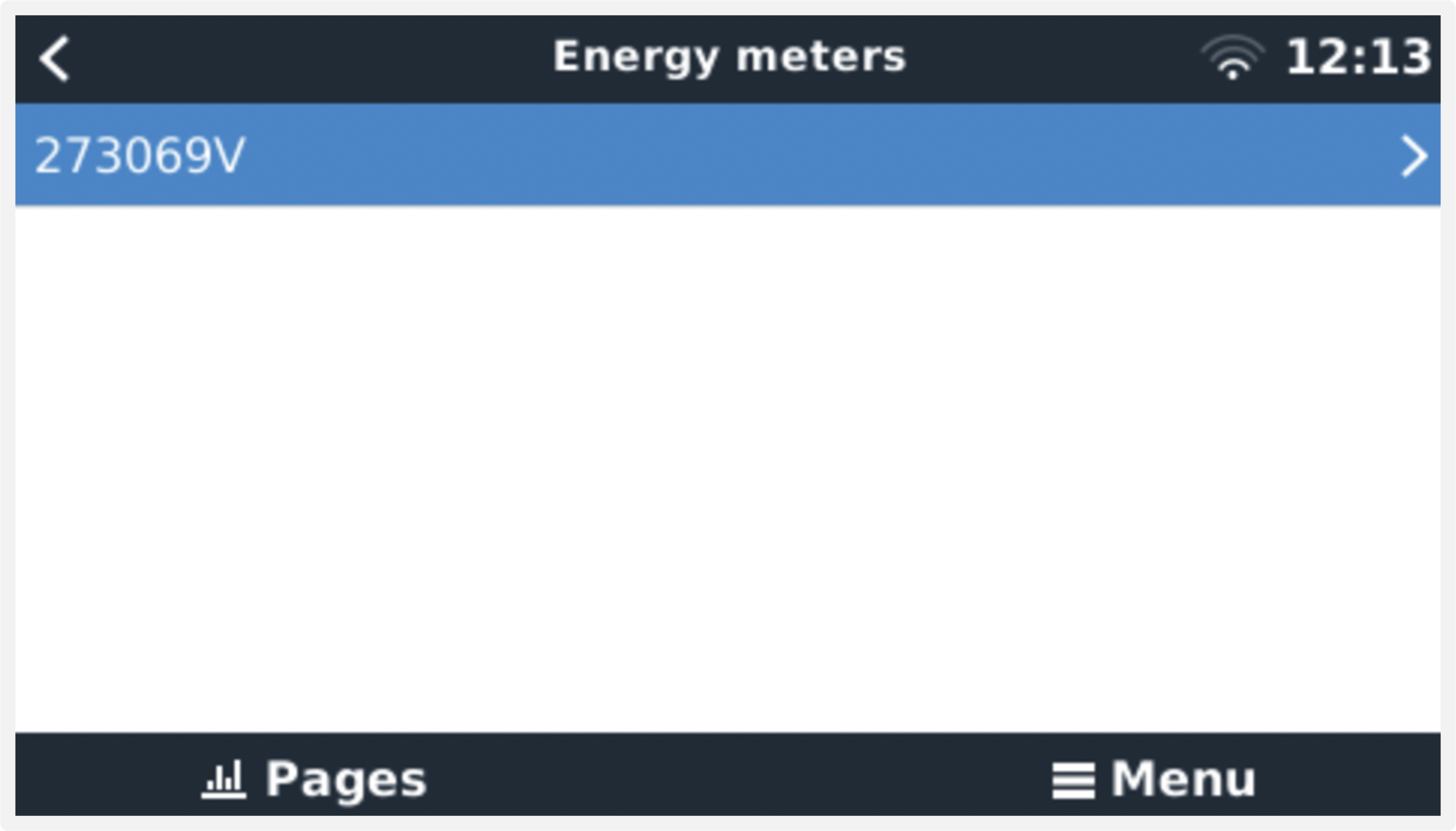 Single Energy Meter in the Energy meters menu | 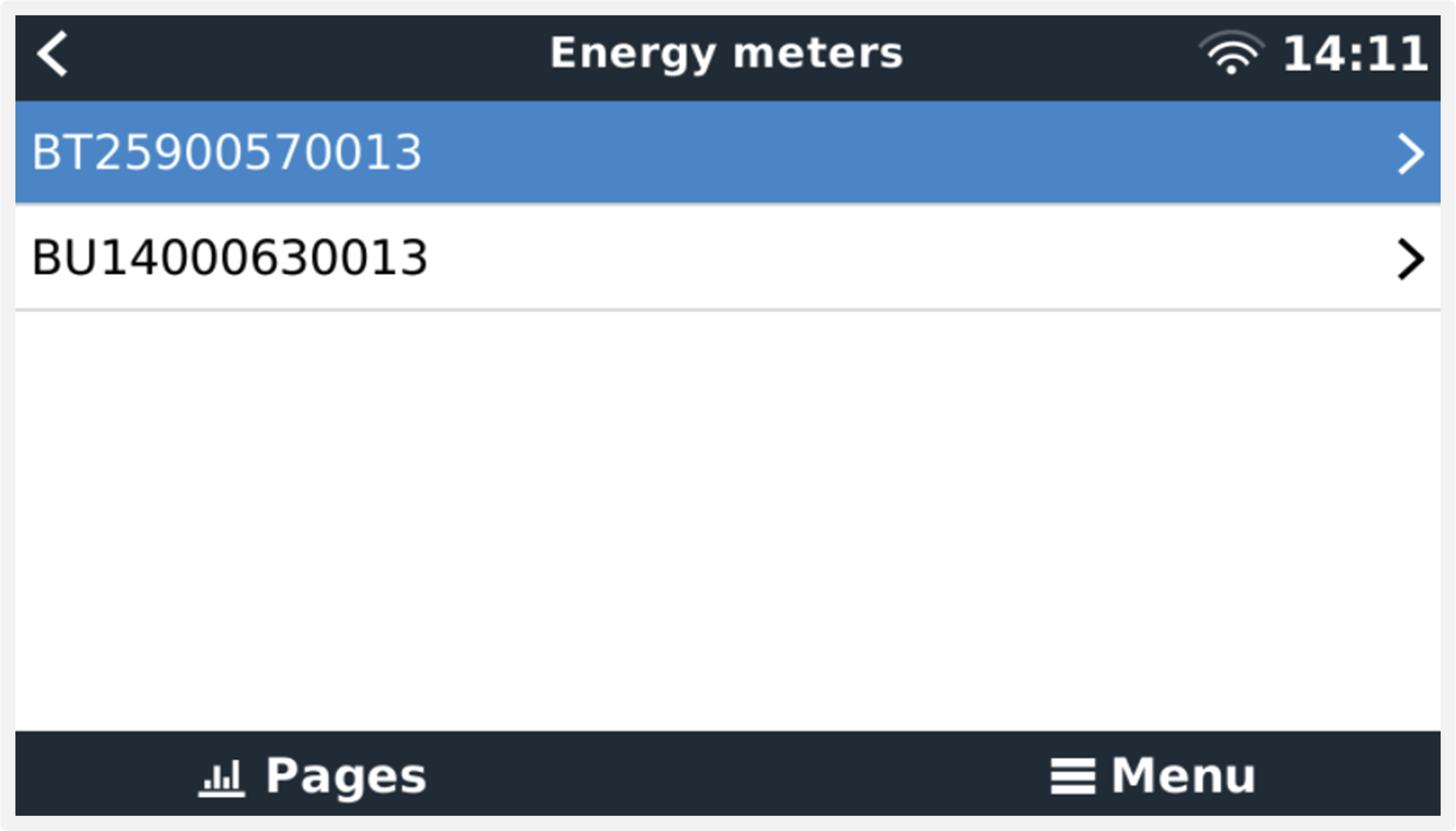 Two Energy Meters in the Energy meters menu |
After selecting an Energy Meter, you have to set the Role and Phase type. Press the space bar or right click to get to the Phase type and Role menu:
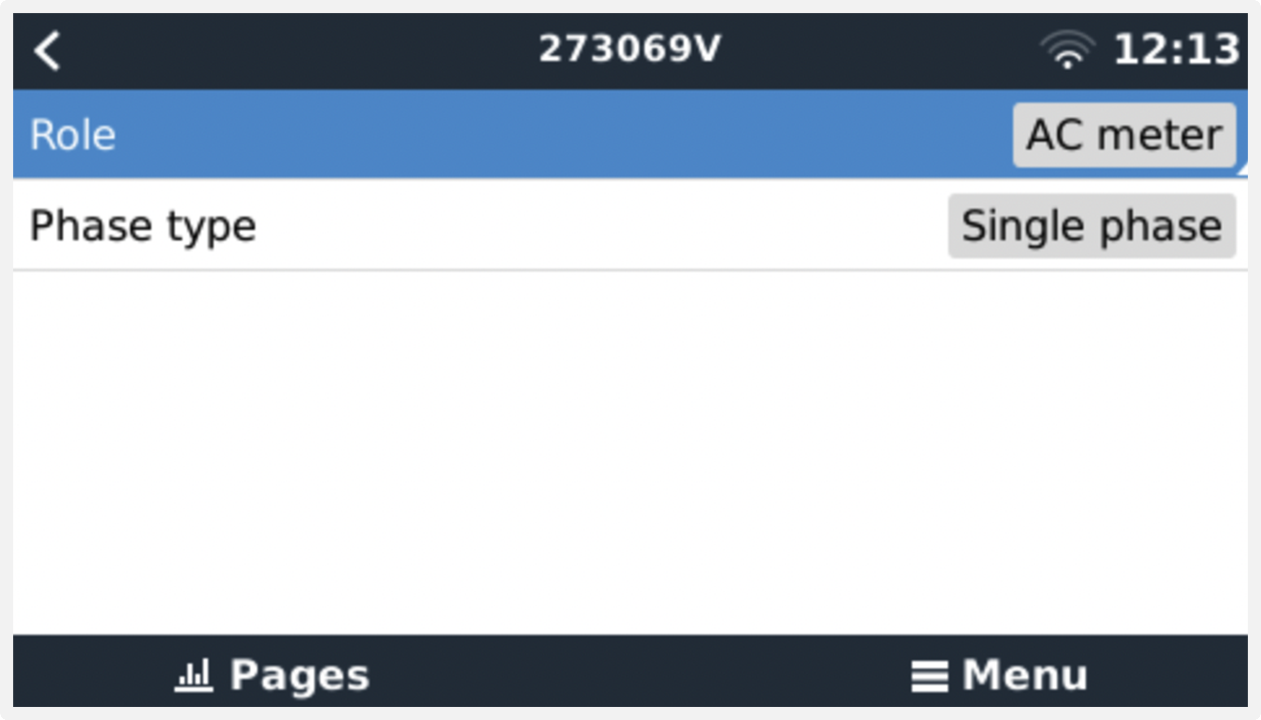 For the ET112 only Single phase option is displayed | 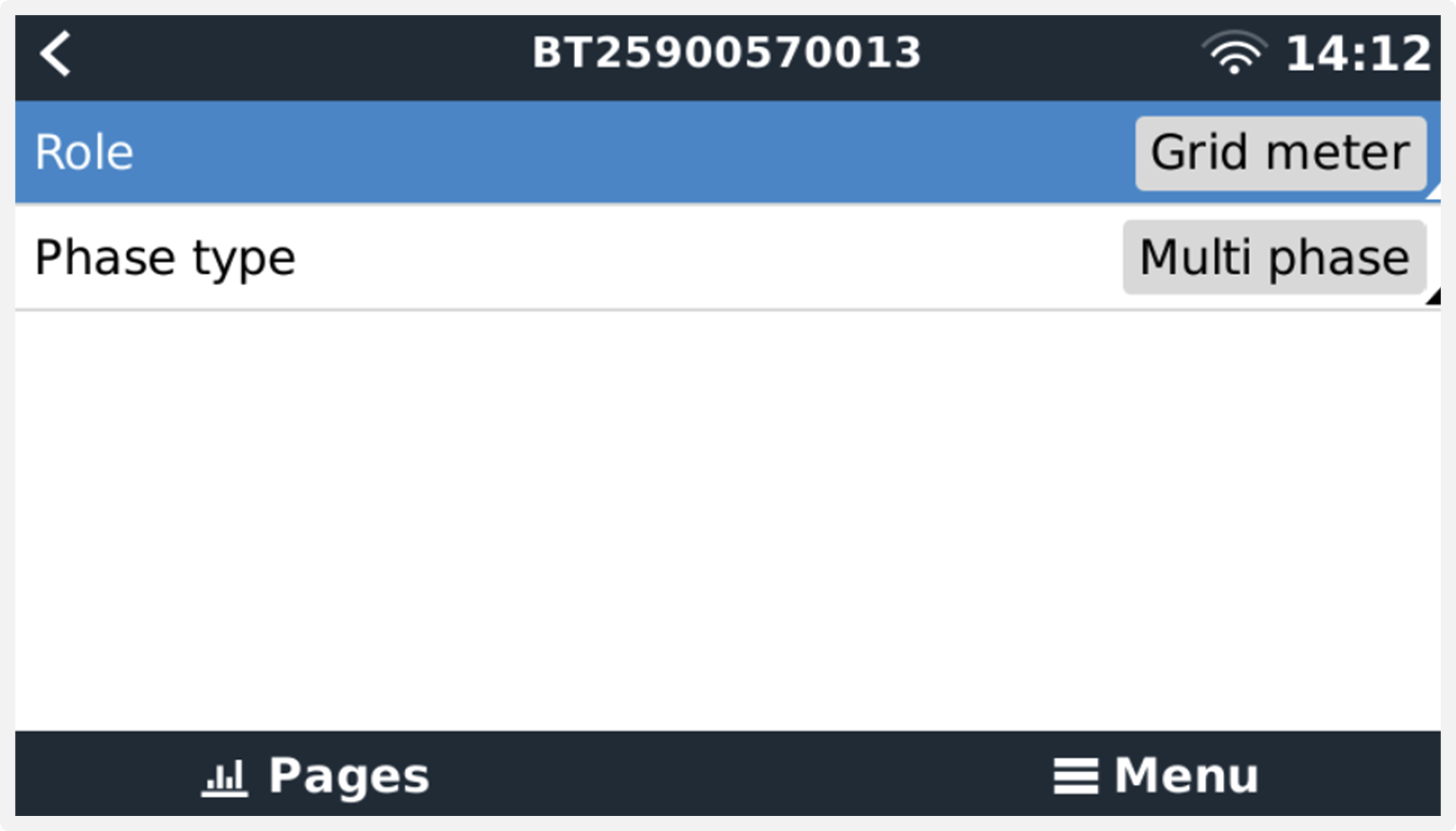 Depending on the application, the role is set here |
Select either Role or Phase type and press the space bar to make changes:
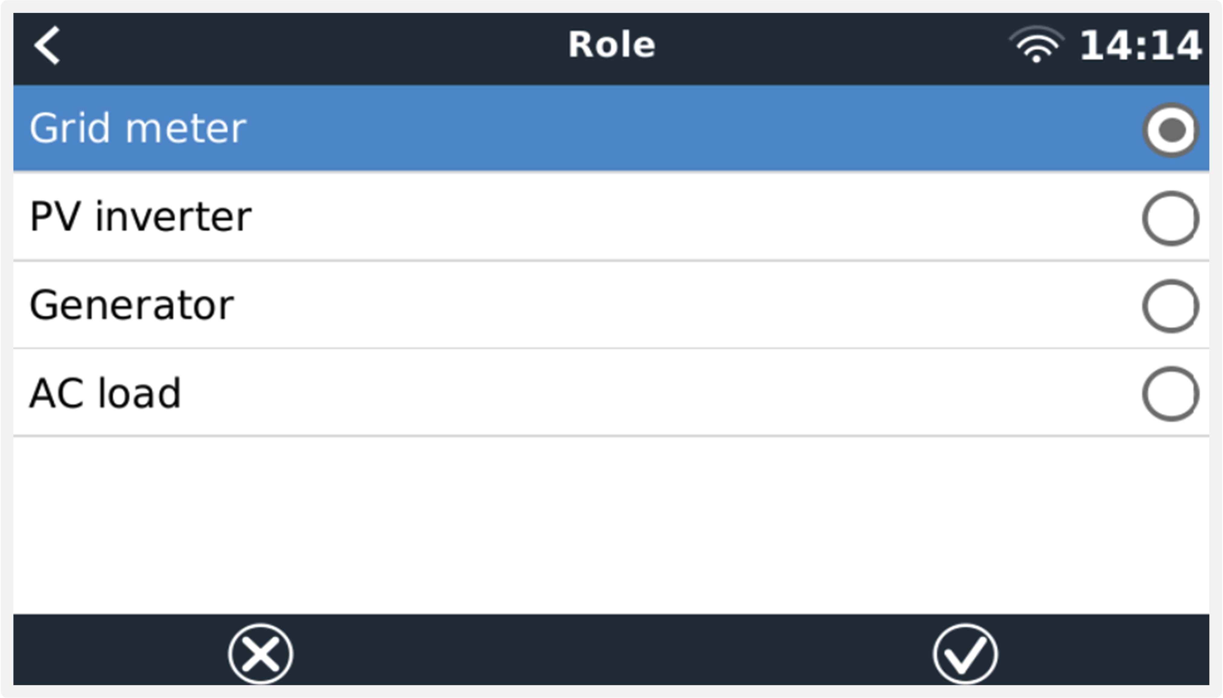 Select the Role according to the application | 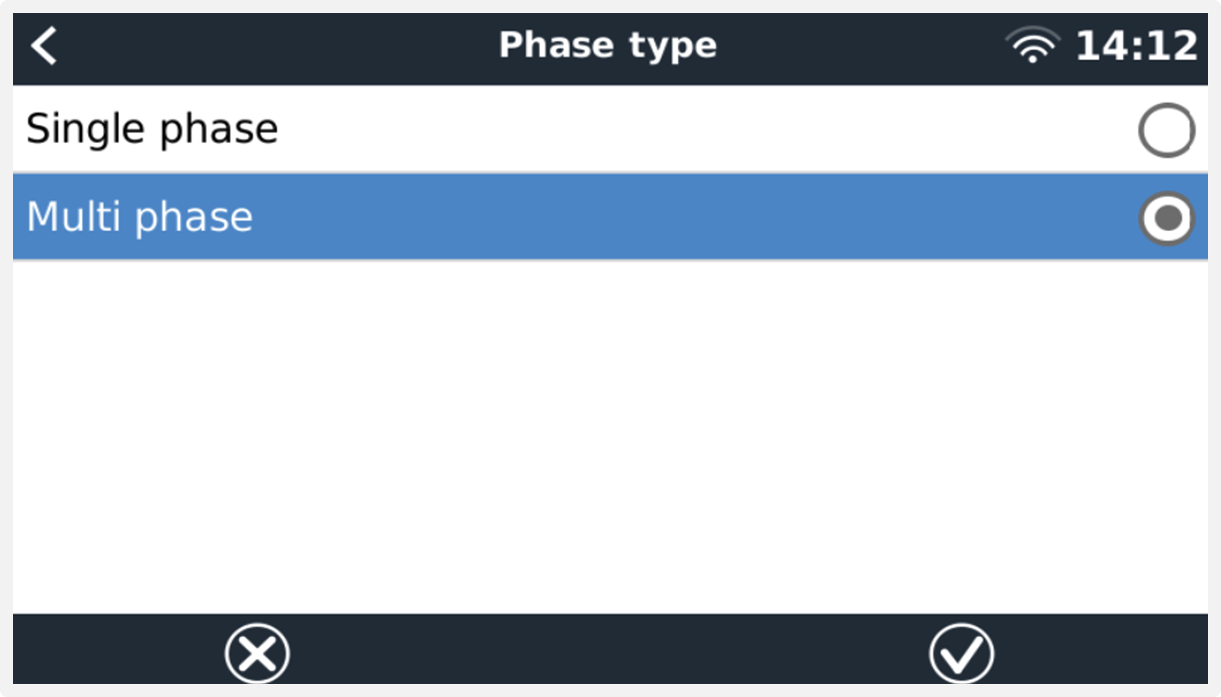 Selection menu for Single and Multi phase type |
Single-phase, single function and single-phase, dual function mode setup:
 Single-phase, single function |  Single-phase, dual function to measure grid on L1 and a PV Inverter on L2. Note that this only applies to the EM540 and ET340. |
After all settings have been made, the Energy Meter now appears with the relevant data in the device list of the GX device:
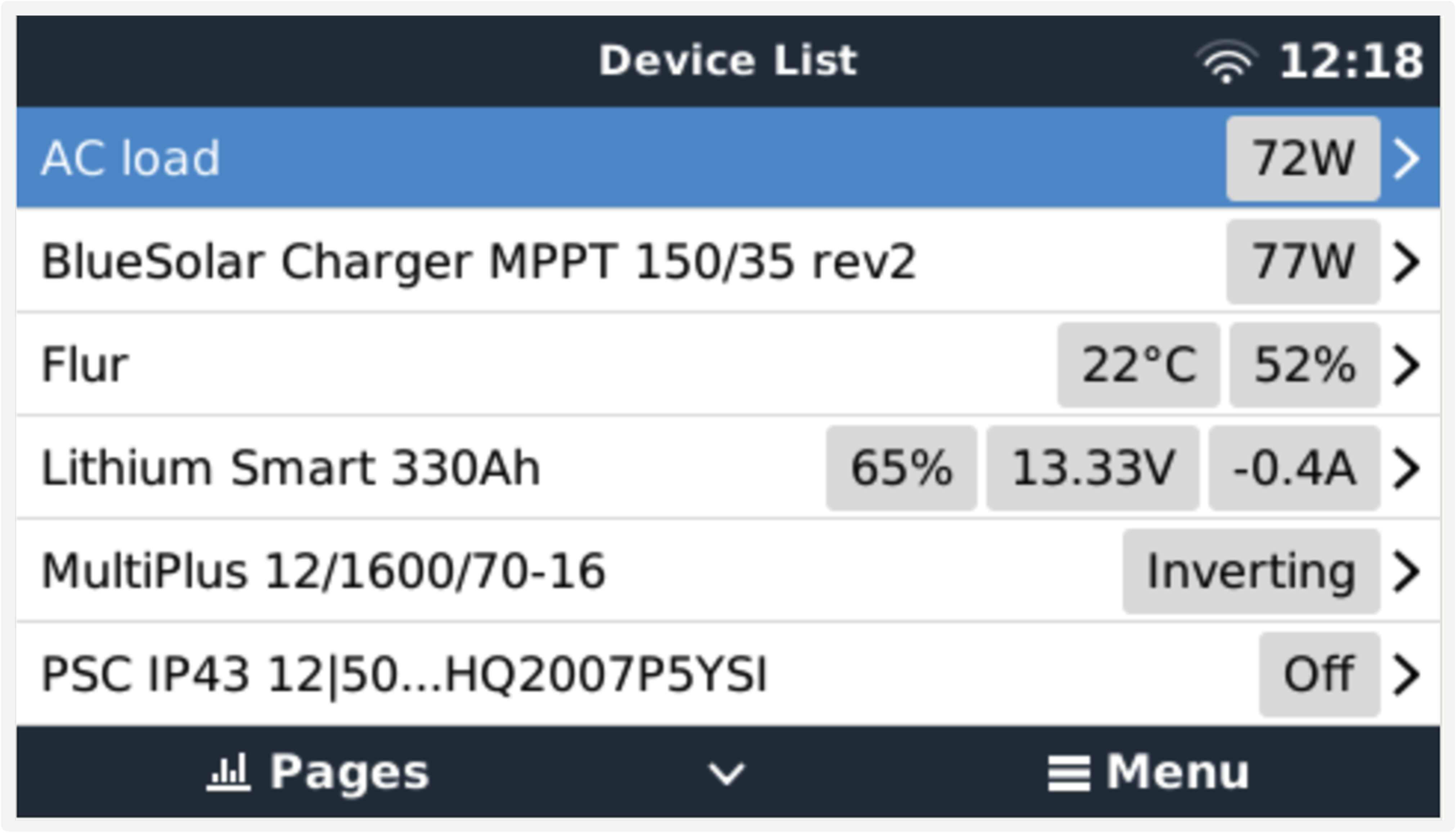 Energy meter set to measure AC loads on the AC output of the inverter/charger | 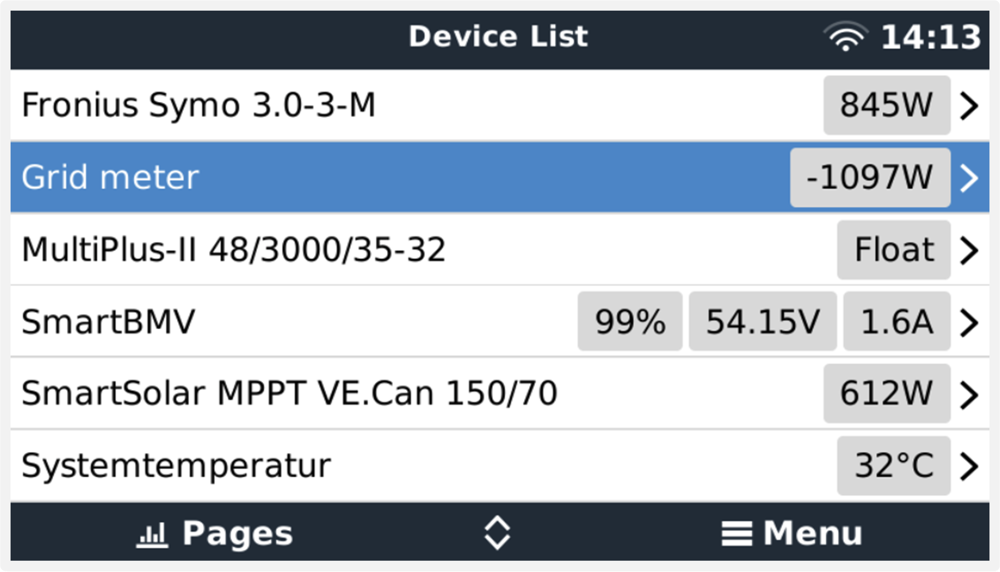 Or configured to measure energy consumption from the grid |
Right-click or press the spacebar to get to the Energy Meter overview with all relevant data on energy consumption and its generation in all phases. At the bottom of the menu, the role of the Energy Meter can be set via the Setup menu. The data used for communication can be read out via the Device menu. You can also set up a custom name for the Energy Meter there:
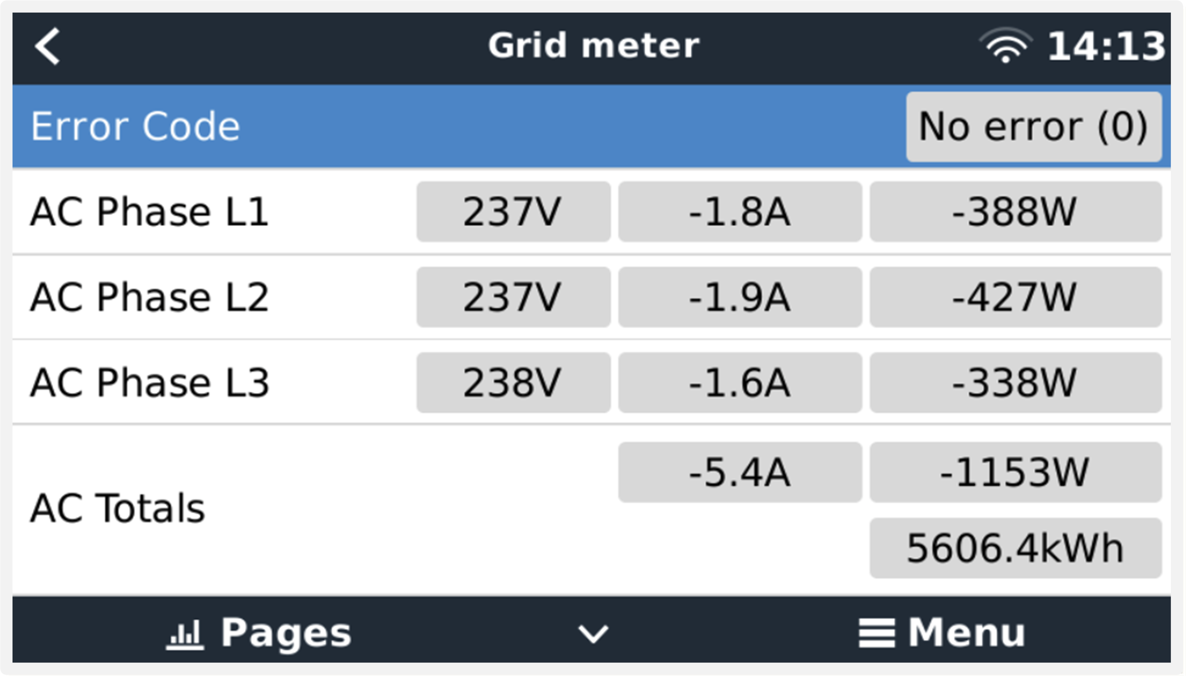 Detailed overview page of a 3-phase Grid meter | 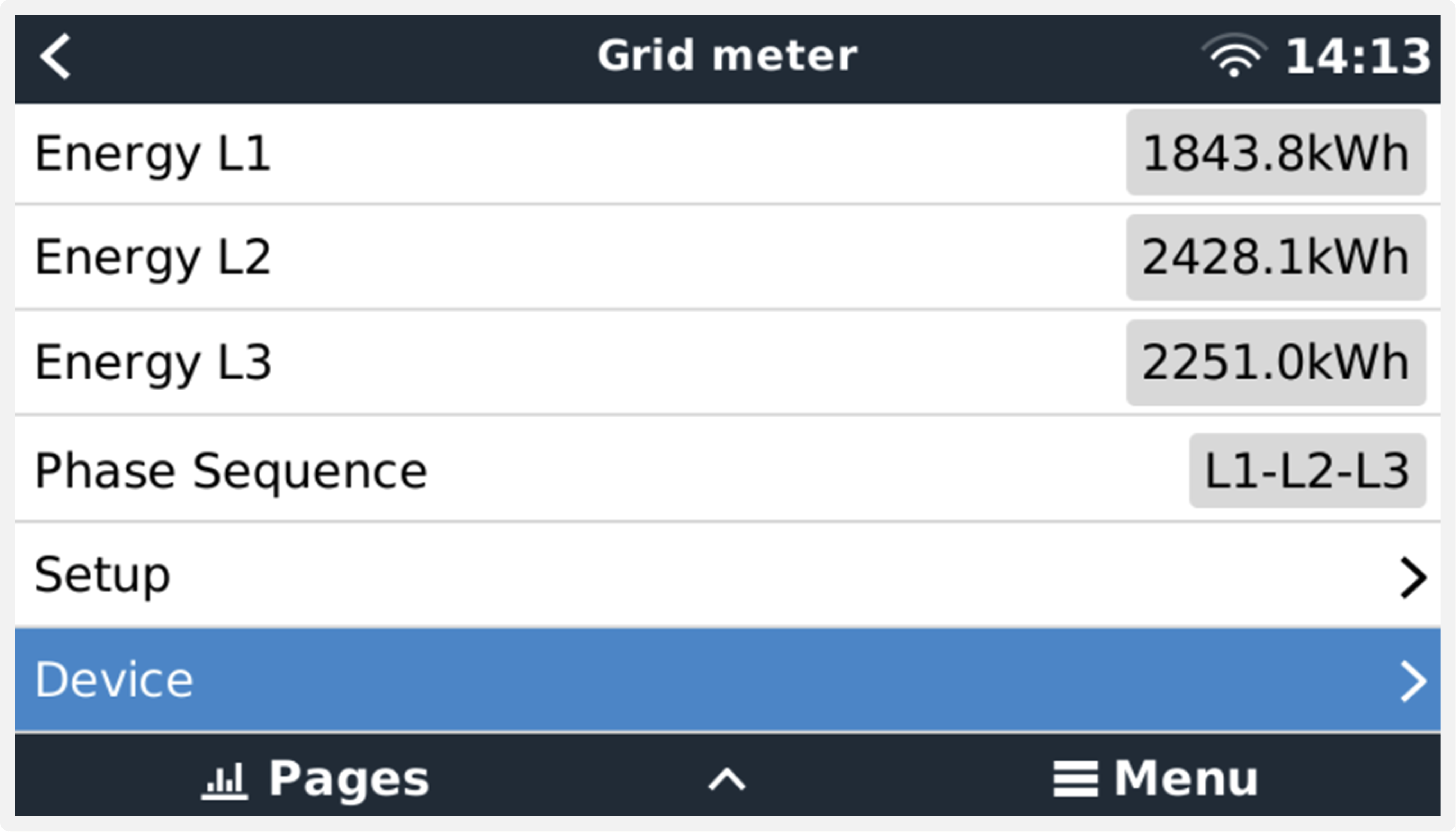 Always be informed about all details, to the second |
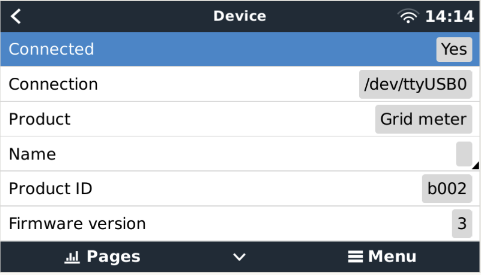 Custom name configuration | 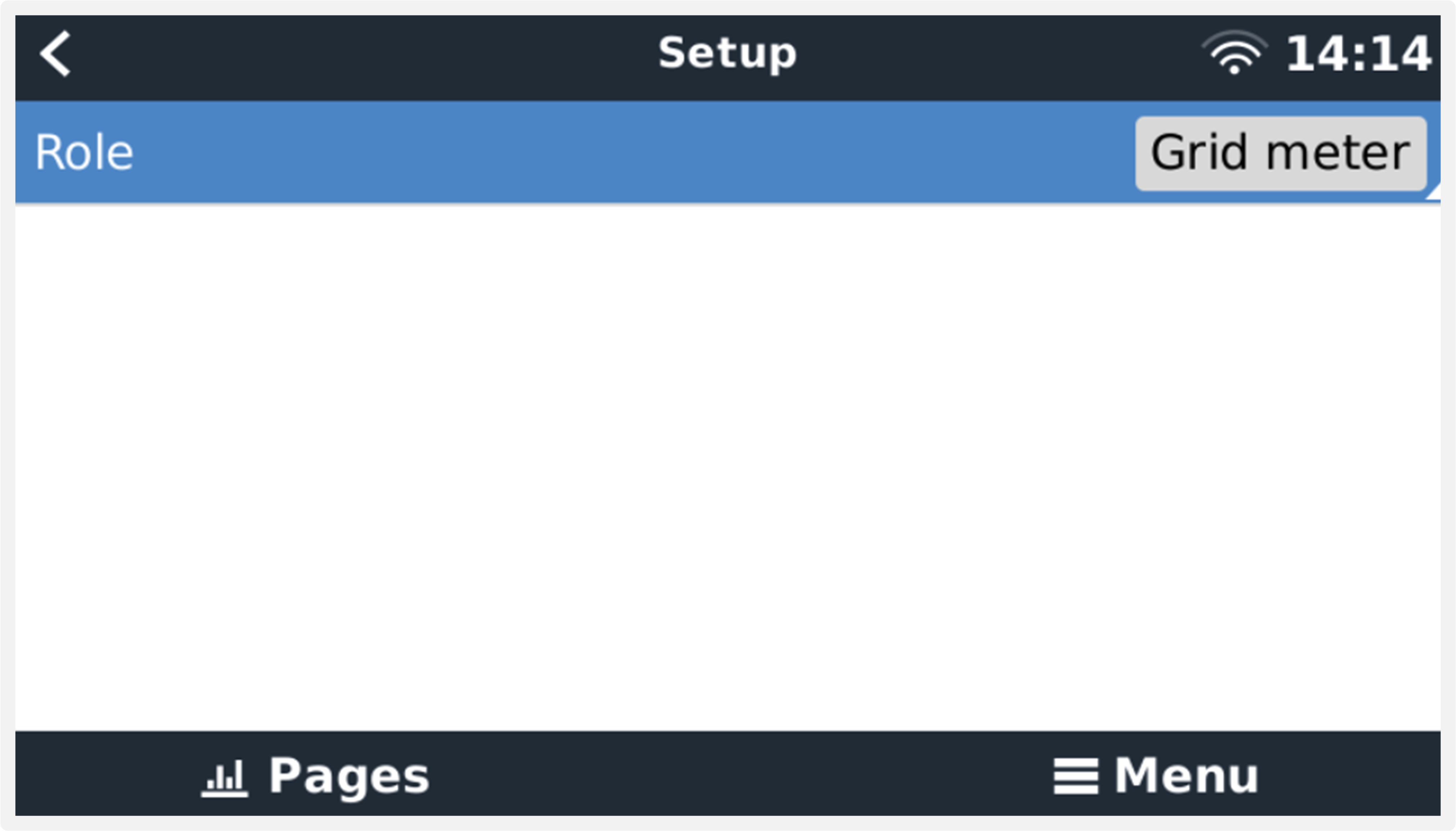 Quickly change roles |