SmartShunt IP65 |
|
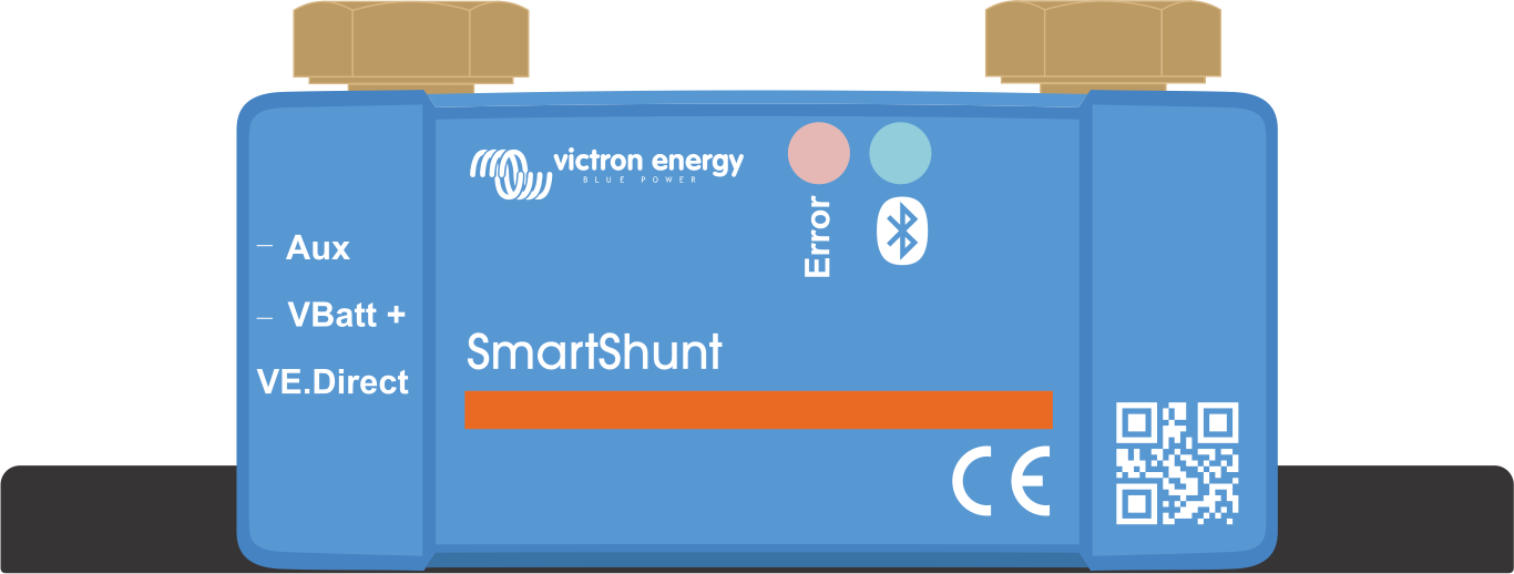
The SmartShunt has two 5.5 mm holes for mounting purposes located in the base of the SmartShunt. The holes can be used to screw or bolt the SmartShunt onto a hard surface (screws are not included).
For the exact location of the mounting holes see the dimension drawing in the appendix of this manual.
 |
Top view SmartShunt IP65 indicating mounting holes and side view SmartShunt indicating mounting method.
# | SmartShunt IP65 connection | Terminal type |
|---|---|---|
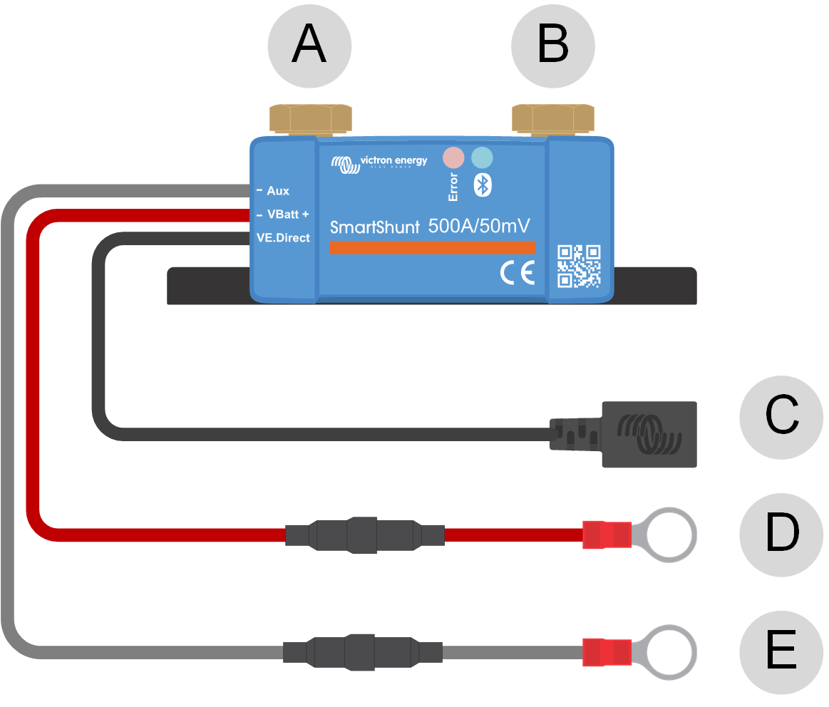
A | LOAD MINUS | M10 bolt (300A model M8) |
B | BATTERY MINUS | M10 bolt (300A model M8) |
C | VE.Direct (black wire) | VE.Direct socket |
D | VBatt+ (red wire with fuse) | M10 ring terminal (300A model M8) |
E | Aux (grey wire with fuse) | M10 ring terminal (300A model M8) |
Connection procedure:
Connect the negative battery terminal to the M10 bolt on the "BATTERY MINUS" side of the shunt. Tighten the shunt bolt with a maximum torque of 21Nm (300A model: 10Nm).
Note that there should be no other connections on this side of the shunt or on the negative battery terminal. Any loads or chargers connected here will be excluded from the battery state of charge calculation.
Connect the negative of the electrical system to the M10 bolt on the "LOAD MINUS" side of the shunt. Tighten the shunt bolt with a maximum torque of 21Nm (300A model: 10Nm). Make sure that the negative of all DC loads, inverters, battery chargers, solar chargers and other charge sources are connected “after” the shunt.
Connect the M10 eye terminal of the red cable with the fuse to the positive terminal of the battery.
The battery monitor is now powered up. .
In order to be fully functional, the battery monitor needs to be configured; see the Configuration chapter.
In case the battery monitor is going to be used to monitor a second battery, battery bank midpoint or battery temperature, see one of the next 3 paragraphs on how to do this and then go to the Configuration chapter.
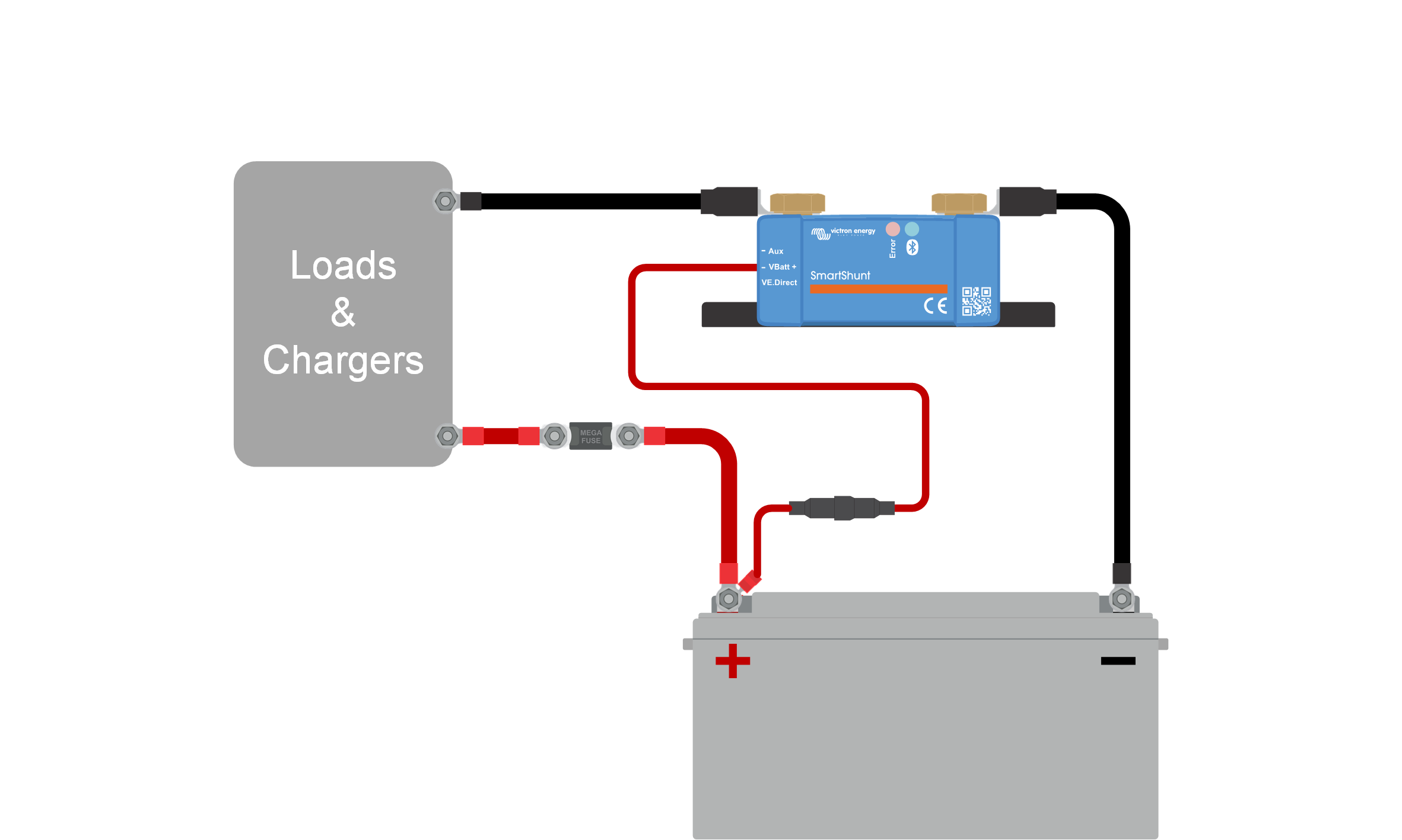 |
Basic battery monitor installation.
In addition to the comprehensive monitoring of the main battery bank, a second parameter can be monitored. This can be one of the following:
The voltage of a second battery, like a starter battery.
The midpoint deviation of the battery bank.
Battery temperature.
This chapter describes how to wire the Aux terminal for the three above options.
For use to monitor the voltage of a second battery, such as a starter or auxiliary battery.
Connection procedure:
Verify that the negative pole of the second battery is connected to the LOAD MINUS side of the shunt.
Connect the M10 lug of the grey "Aux" cable to the positive terminal of the second battery.
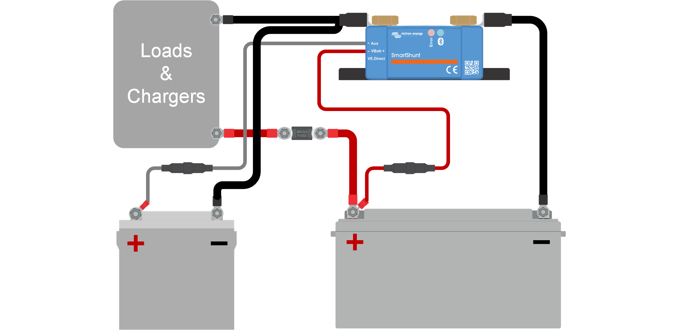 |
Battery monitor with auxiliary second battery monitoring.
For use with a battery bank that consists of multiple batteries that are wired in series or series/parallel to create a 24V or 48V battery bank.
Connection procedure:
Connect the M10 lug of the grey "Aux" cable to the positive terminal of the midpoint.
For more information on midpoint monitoring and for additional diagrams on midpoint battery bank wiring see the Midpoint voltage monitoring chapter.
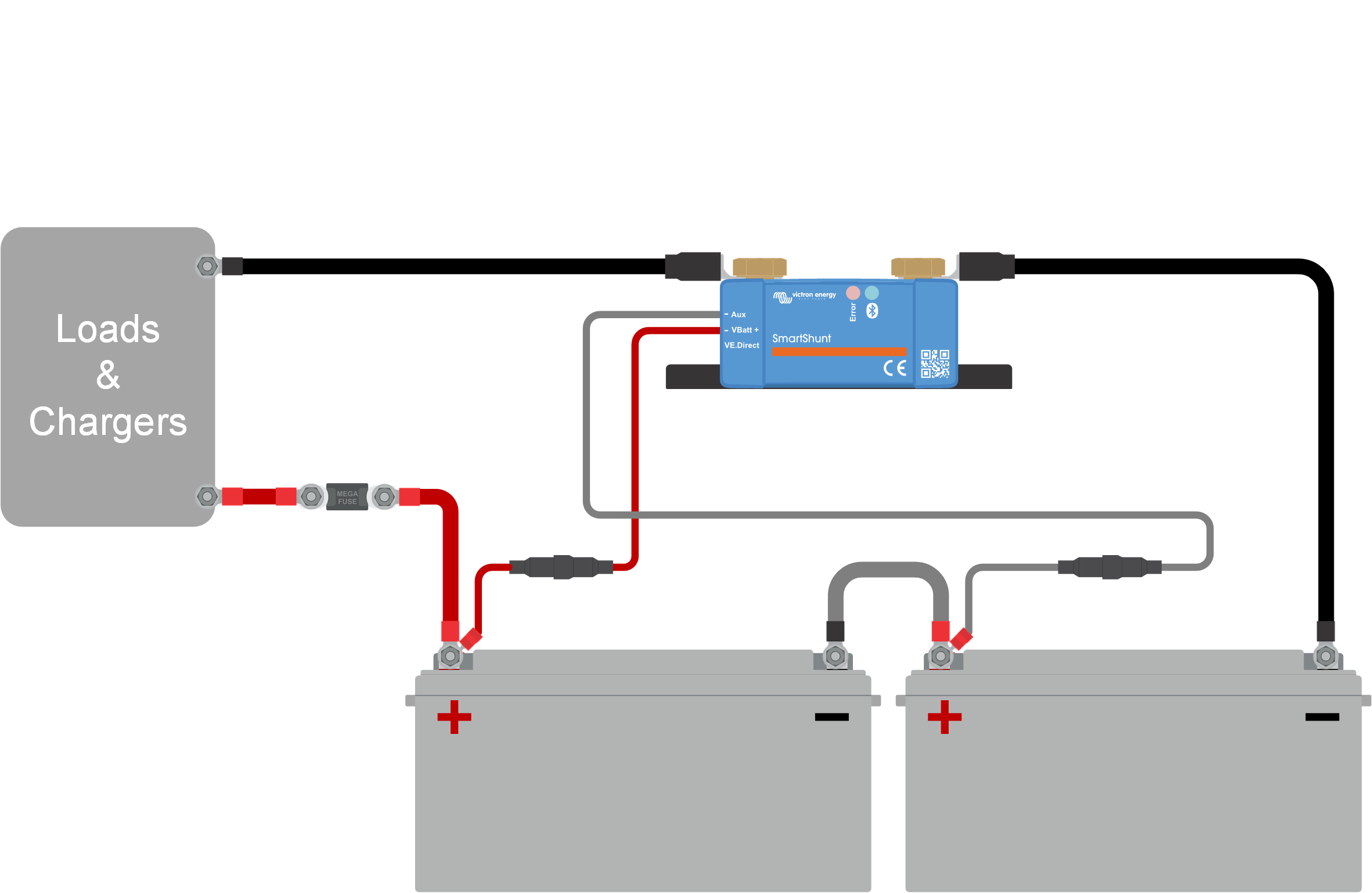 |
Battery monitor with auxiliary midpoint monitoring.
For use to monitor the temperature of a battery via the (not included) Temperature sensor for BMV-712 Smart and BMV-702 . This temperature sensor needs to be purchased separately. Be aware that this is a different temperature sensor than the temperature sensors that are included with Victron inverter/chargers and some battery chargers.
Temperature sensor for the battery monitor
Connection procedure:
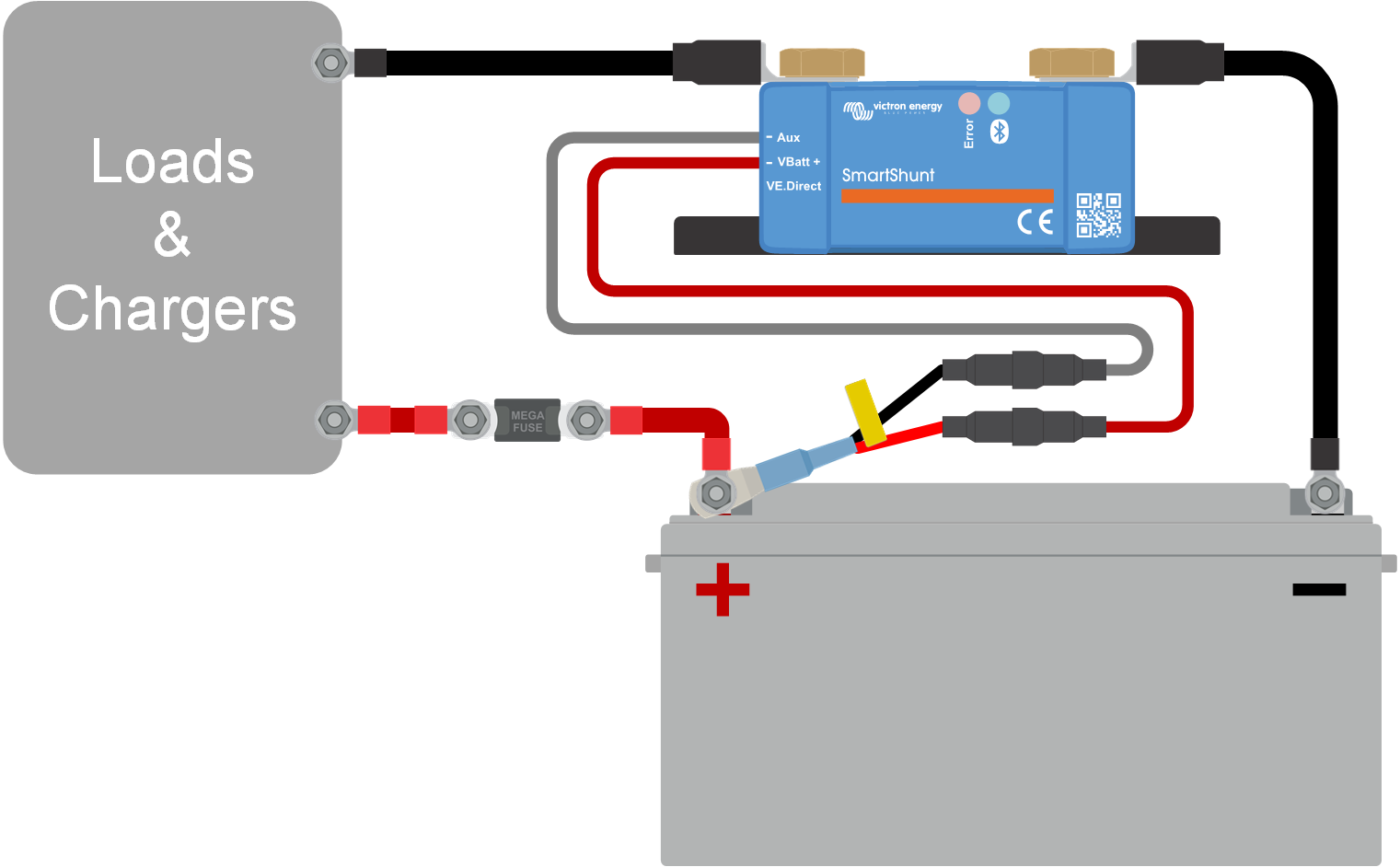 |
Battery monitor with auxiliary temperature sensing.
Note
Note that the temperature sensor wires do not easily connect to the SmartShunt wires. You will have to make your own provision that the connection between the temperature sensor and the SmartShunt is made in a safe and electrical sound way.
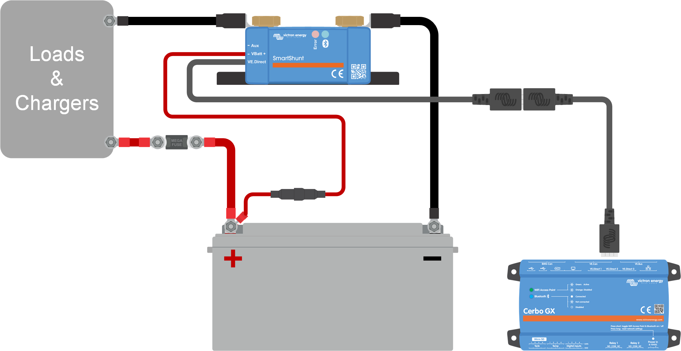
If the system contains a GX device such as a Cerbo GX, the battery monitor can be connected to the GX device using a VE.Direct cable or a VE.Direct to USB interface.
Once connected, the GX device can be used to read out all monitored battery parameters. For more information see chapter Connecting to a GX device and the VRM portal.
When using the battery monitor as a DC meter, wire it to the device or circuit that needs to be monitored.
Note
Note that the battery monitor also needs to be configured as a DC monitor using the VictronConnect app before it will operate as a DC monitor. See the Configure for use as DC meter chapter.
It is also possible to have a main battery monitor in the system together with a separate battery monitor that has been set up as a DC meter to monitor a specific device or circuit.
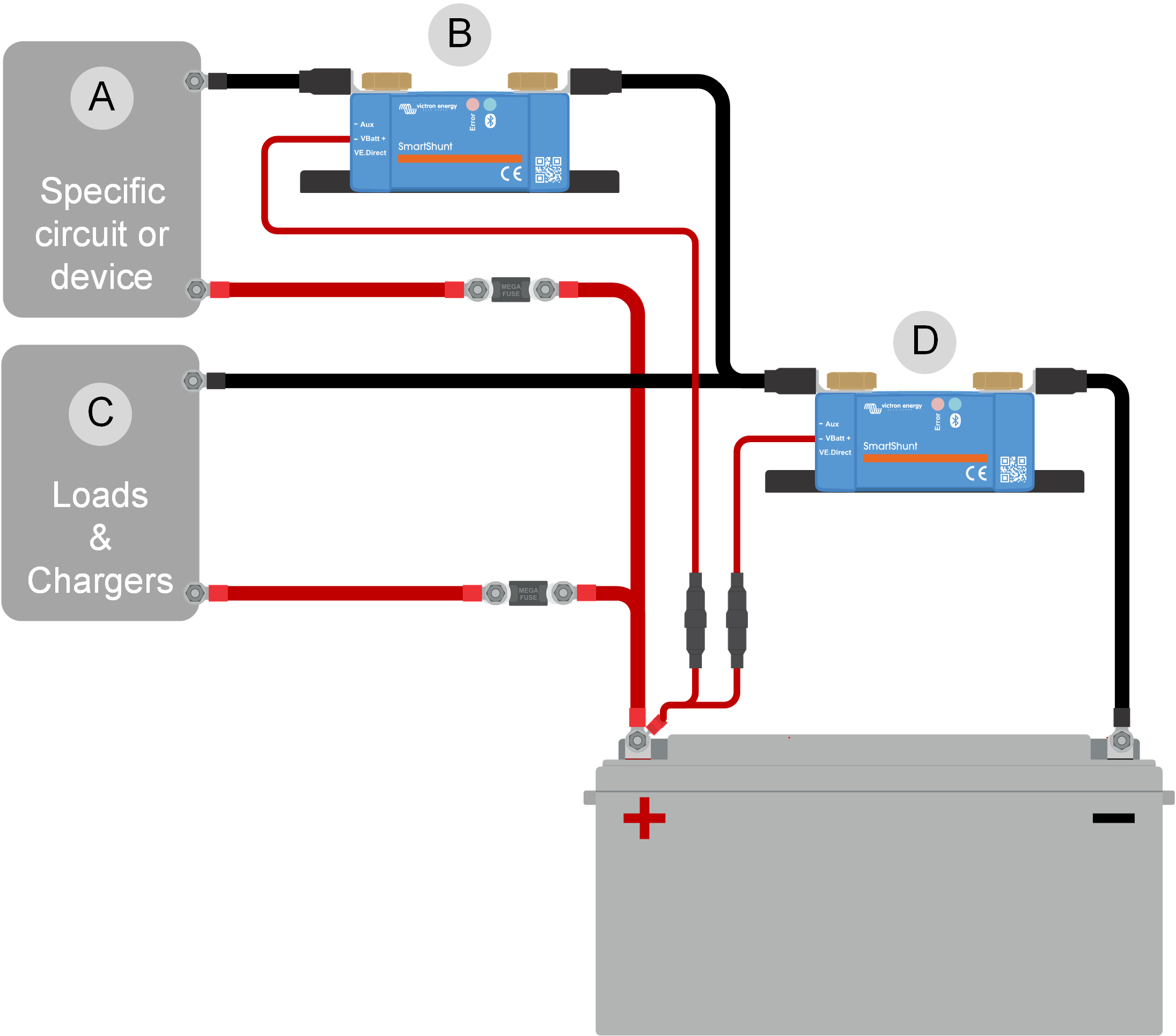 |
Wiring example of a system containing a main battery monitor, together with a battery monitor that has been set up as a DC meter and is monitoring a specific device or circuit. One battery monitor is used as a DC meter (B) and the other battery monitor is used as a battery monitor (D).
# | Description |
|---|---|
A | Specific DC device or DC circuit |
B | Battery monitor used as DC meter |
C | The rest of the DC circuit |
D | Battery monitor used as battery monitor |
