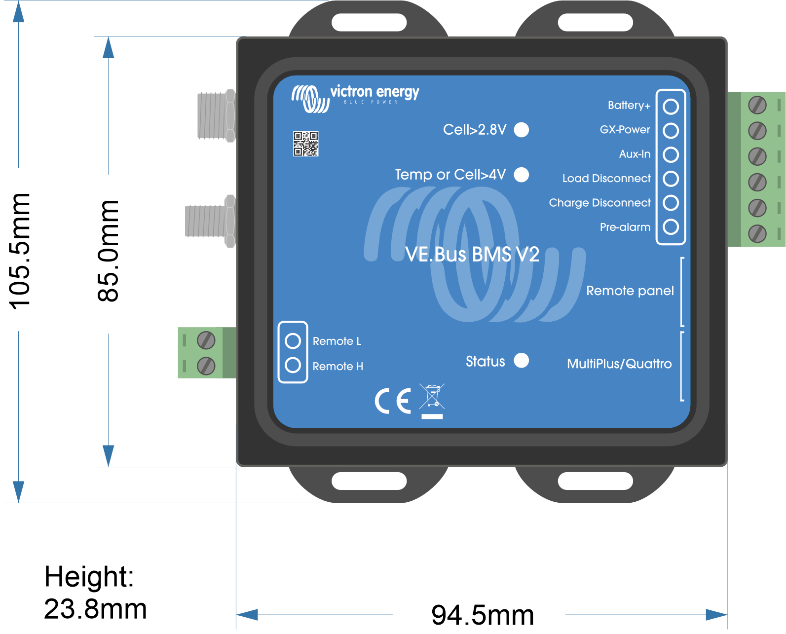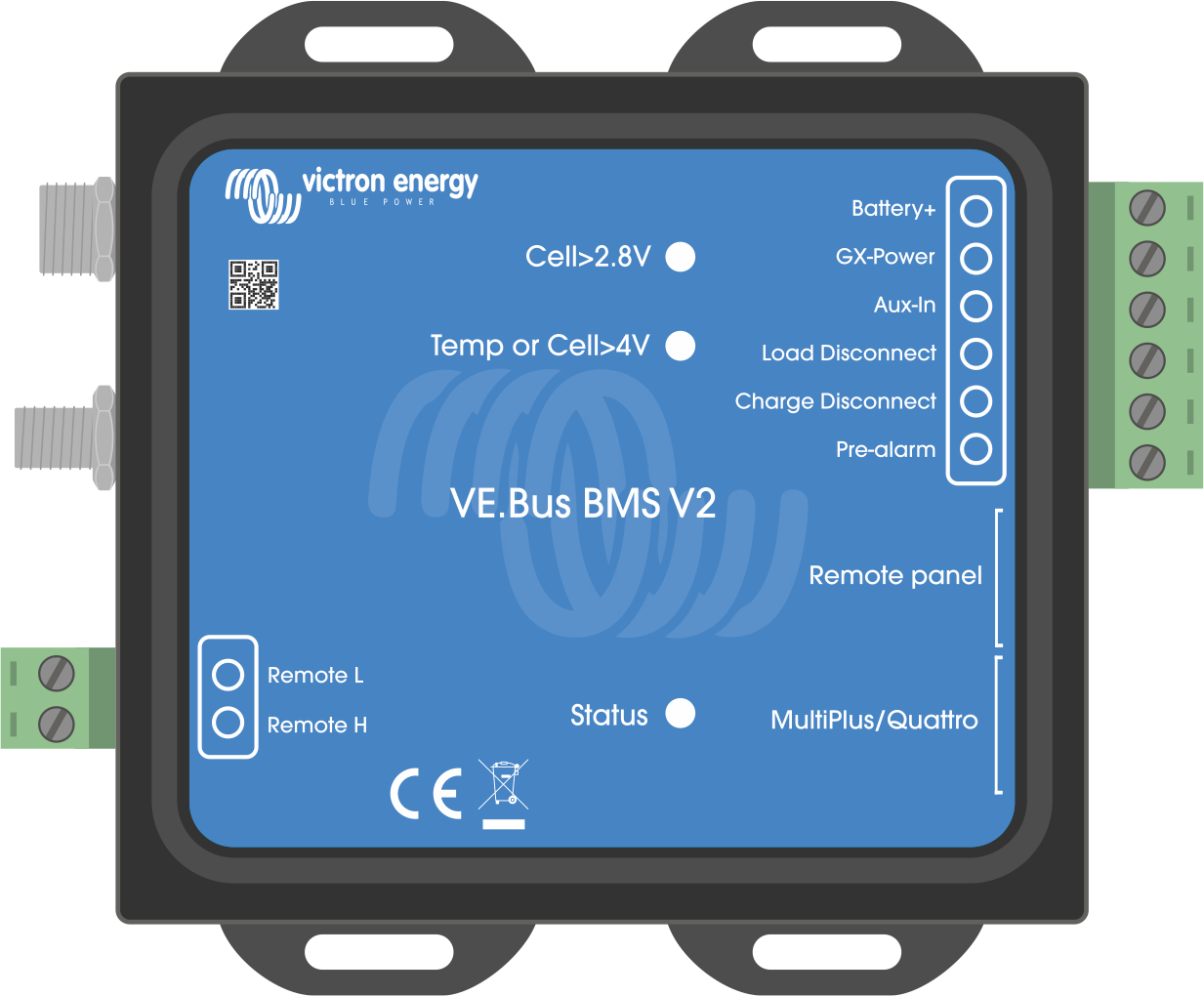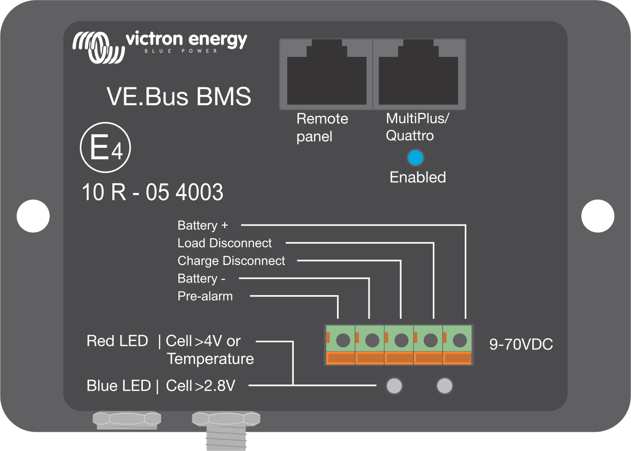
This table highlights the differences between the VE.Bus BMS V2 compared to it's predecessor, the VE.Bus BMS V1.
Feature | VE.Bus BMS V2 | VE. Bus BMS V1 | ||
|---|---|---|---|---|
Product image |
|
| ||
MultiPlus/Quattro VE.Bus port | Yes | Yes | ||
Remote panel VE.Bus port | To connect a GX device, a VE.Bus Smart dongle or a Digital Multi Control. | Only to connect a Digital Multi Control. | ||
GX device communication | Yes, the BMS broadcasts operational data and the BMS can control equipment that is connected to a GX device, like solar chargers and certain AC chargers via DVCC. | No | ||
On/Off/Charger-only control | Yes, via GX device and remotely via VRM, VE.Bus Smart dongle and Digital Multi Control. | Only with Digital Multi Control. | ||
GX-Pow terminal | Yes, the GX-Pow output supplies GX power from either the battery or from the Aux-In input, whichever voltage is higher. | No | ||
BMS firmware update | Yes, both locally and also remotely via the VRM portal. | Not possible | ||
Inverter/charger "in system" firmware update | Yes, both locally and also remotely via the VRM portal. | No, the VE.Bus BMS V1 needs to be disconnected in order to update the firmware of the inverter/charger. | ||
Usable without a VE.Bus connection | No. The BMS has no battery minus connection, battery minus is supplied by the VE.Bus and VE.Bus needs to be connected for the BMS to be powered. | Yes | ||
Load disconnect terminal | Yes | Yes | ||
Pre-alarm terminal | Yes | Yes | ||
Charge disconnect terminal | Yes | Yes | ||
Remote on/off terminal | Yes | No. If remote on/off control is needed, a switch needs to be placed in the positive power supply line to the BMS. | ||
Aux-In terminal | Yes, an AC-DC adapter or other power supply connected to the Aux-In input ensures that the GX device is also powered during a low cell state as long as that aux power is available. | No | ||
MultiPlus/Quattro enabled LED | No | Yes | ||
Status LED | Yes, this LED indicates that the BMS is sending information frames to the inverter/charger. The LED can also indicate if the BMS is stuck in boot loader mode. | No | ||
Low cell voltage LED | Yes | Yes | ||
High cell voltage and/or temperature LED | Yes | Yes |

